Toyota Tacoma (2015-2018) Service Manual: Inspection
INSPECTION
PROCEDURE
1. REMOVE SPIRAL CABLE SUB-ASSEMBLY WITH SENSOR
(a) If there are any defects as mentioned below, replace the spiral cable sub-assembly with a new one:
Scratches, cracks, dents or chips on the connector or the spiral cable sub-assembly.
|
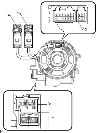
(b) Inspect the spiral cable sub-assembly. (1) Set the spiral cable in the center, and measure the resistance in each position where the spiral cable is turned 2.5 times clockwise and counterclockwise. (2) Turn the spiral cable 2.5 times clockwise from its original position and measure the resistance while turning it 5 times counterclockwise. Text in Illustration
Standard resistance:
NOTICE: As the spiral cable sub-assembly may break, do not rotate the spiral cable sub-assembly more than the specified amount. |
|
 Removal
REMOVAL
PROCEDURE
1. REMOVE STEERING PAD
(See page
)
2. REMOVE STEERING WHEEL ASSEMBLY
3. REMOVE LOWER STEERING COLUMN COVER
4. REMOVE UPPER STEERING COLUMN COVER
5. REMOVE SPIR ...
 Installation
INSTALLATION
PROCEDURE
1. INSTALL SPIRAL CABLE SUB-ASSEMBLY WITH SENSOR
(a) Check that the ignition switch is OFF.
(b) Check that the batt ...
Other materials:
System Diagram
SYSTEM DIAGRAM
HINT:
Each tire pressure warning valve and transmitter sends its transmitter ID, temperature
and tire pressure information to the tire pressure warning ECU and receiver.
Transmitting ECU (Transmitter)
Receiving ECU
Signal
Communicat ...
Lost Communication with Front Camera Module (U023A)
DESCRIPTION
These DTCs are stored when the CAN communication system is malfunctioning.
DTC No.
DTC Detecting Condition
Trouble Area
U023A
Lost Communication With Image Processing Module"A"
The main body ECU ...
Dtc Check / Clear
DTC CHECK / CLEAR
CHECK DTC
(a) Connect the Techstream to the DLC3.
(b) Turn the ignition switch to ON.
(c) Turn the Techstream on.
(d) Enter the following menus: Chassis / LKA/LDA / Trouble Codes.
(e) Check for DTCs.
Click here
CLEAR DTC
(a) Connect the Techstream to the DLC3.
(b) Turn ...
