Toyota Tacoma (2015-2018) Service Manual: Terminals Of Ecu
TERMINALS OF ECU
NOTICE:
- DTCs may be output when connectors are disconnected during inspection. Therefore, be sure to clear the DTCs using the Techstream once the inspection has been completed.
- Do not apply excessive force to the f5 forward recognition camera connector.
CHECK FORWARD RECOGNITION CAMERA
(a) Disconnect the forward recognition camera connector.

|
*a |
Front view of wire harness connector (to Forward Recognition Camera) |
- |
- |
(b) Measure the voltage and resistance according to the value(s) in the table below.
|
Terminal No. (Symbol) |
Wiring Color |
Terminal Description |
Condition |
Specified Condition |
|---|---|---|---|---|
|
F46-7 (IGB) - F46-10 (GND) |
BE - W-B |
Power source |
Ignition switch ON |
11 to 14 V |
|
Ignition switch off |
Below 1 V |
|||
|
F46-10 (GND) - Body ground |
W-B - Body ground |
Ground |
Always |
Below 1 Ω |
(c) Reconnect the forward recognition camera connector.

|
*a |
Component with harness connected (Forward Recognition Camera) |
- |
- |
(d) Measure the voltage according to the value(s) in the table below.
|
Terminal No. (Symbol) |
Wiring Color |
Terminal Description |
Condition |
Specified Condition |
|---|---|---|---|---|
|
F46-1 (HTR) - F46-10 (GND) |
R - W-B |
Camera heater (forward recognition hood) operation signal |
Ignition switch ON, camera heater (forward recognition hood) not operating |
11 to 14 V |
|
Ignition switch ON, camera heater (forward recognition hood) operating |
0 to 1.5 V |
|||
|
F46-8 (BZ) - F46-10 (GND) |
L - W-B |
Skid control buzzer |
Ignition switch ON, skid control buzzer not operating |
11 to 14 V |
|
Ignition switch ON, skid control buzzer operating |
0 to 1.5 V |
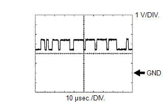
(e) Check for pulses according to the value(s) in the table below.
HINT:
If the waveform is not similar to that shown in the illustration, a malfunction of a CAN bus line, terminating resistor, or the forward recognition camera is suspected.
|
Terminal No. (Symbol) |
Wiring Color |
Terminal Description |
Condition |
Specified Condition |
|---|---|---|---|---|
|
F46-5 (CA1P) - F46-10 (GND) |
L - W-B |
CAN communication signal |
Ignition switch ON |
Pulse generation (See waveform 1) |
|
F46-11 (CA1N) - F46-10 (GND) |
W - W-B |
CAN communication signal |
Ignition switch ON |
Pulse generation (See waveform 2) |
|
F46-6 (CANH) - F46-10 (GND) |
B - W-B |
CAN communication signal |
Ignition switch ON |
Pulse generation (See waveform 1) |
|
F46-12 (CANL) - F46-10 (GND) |
W - W-B |
CAN communication signal |
Ignition switch ON |
Pulse generation (See waveform 2) |
(1) Waveform 1
|
Item |
Content |
|---|---|
|
Terminal Name |
Between F46-5 (CA1P) and F46-10 (GND) Between F46-6 (CANH) and F46-10 (GND) |
|
Tester Range |
1 V/DIV., 10 ÎĽsec./DIV. |
|
Condition |
Ignition switch ON |
HINT:
The waveform varies depending on the CAN communication signal.
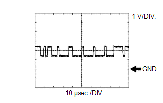
(2) Waveform 2
|
Item |
Content |
|---|---|
|
Terminal Name |
Between F46-11 (CA1N) and F46-10 (GND) Between F46-12 (CANL) and F46-10 (GND) |
|
Tester Range |
1 V/DIV., 10 ÎĽsec./DIV. |
|
Condition |
Ignition switch ON |
HINT:
The waveform varies depending on the CAN communication signal.
 Dtc Check / Clear
DTC CHECK / CLEAR
CHECK DTC
(a) Connect the Techstream to the DLC3.
(b) Turn the ignition switch to ON.
(c) Turn the Techstream on.
(d) Enter the following menus: Chassis / Front Recognition Came ...
 Fail-safe Chart
FAIL-SAFE CHART
FAIL-SAFE FUNCTION
(a) If a malfunction is detected in the forward recognition camera system, the
systems that use the forward recognition camera perform the fail-safe function. ...
Other materials:
Parts Location
PARTS LOCATION
ILLUSTRATION
ILLUSTRATION
ILLUSTRATION
ILLUSTRATION
...
Removal
REMOVAL
PROCEDURE
1. REMOVE RADIATOR GRILLE
(a) w/ Toyota Safety Sense P
(1) Disconnect the connector.
(2) Disengage the clamp.
(b) Put protective tape around the radiator grille.
...
Reassembly
REASSEMBLY
CAUTION / NOTICE / HINT
NOTICE:
Do not try to remove the black nylon tube as it is welded to the fuel suction
tube assembly (See page
).
HINT:
Perform "Inspection After Repairs" after replacing the fuel pump (See page
).
PROCEDURE
1. INSTALL FUEL PUMP
HINT:
Perfo ...
