Toyota Tacoma (2015-2018) Service Manual: Extension Housing Rear Oil Seal
Components
COMPONENTS
ILLUSTRATION
Replacement
REPLACEMENT
PROCEDURE
1. REMOVE PROPELLER SHAFT WITH CENTER BEARING ASSEMBLY
(See page .gif) )
)
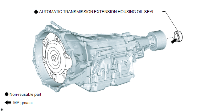
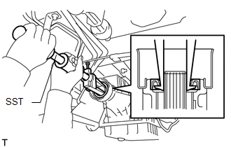
2. REMOVE AUTOMATIC TRANSMISSION EXTENSION HOUSING OIL SEAL
|
(a) Using SST, remove the automatic transmission extension housing oil seal. SST: 09308-00010 |
|
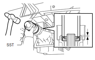
3. INSTALL AUTOMATIC TRANSMISSION EXTENSION HOUSING OIL SEAL
(a) Coat the lip of a new automatic transmission extension housing oil seal with MP grease.
|
(b) Using SST and a hammer, drive in the automatic transmission extension housing oil seal. SST: 09309-37010 Standard depth: 5.4 to 5.8 mm (0.213 to 0.228 in.) NOTICE:
|
|
4. INSTALL PROPELLER SHAFT WITH CENTER BEARING ASSEMBLY
(See page )
 Transmission Control Switch Circuit
DESCRIPTION
After moving the shift lever to S, it is possible to switch the shift range between
"1" (S1 range) and "6" (S6 range) using the transmission control switch.
Moving ...

Other materials:
Lost Communication with ECM / PCM "A" (U0100,U0122)
DESCRIPTION
This DTC is output when communication is lost with the skid control ECU (brake
actuator assembly) or ECM.
DTC No.
Detection Item
DTC Detection Condition
Trouble Area
U0100
Lost Communication with ECM / PCM " ...
Problem Symptoms Table
PROBLEM SYMPTOMS TABLE
HINT:
Troubleshooting of the theft deterrent system is based on the premise
that the power door lock control system, wireless door lock control system*1
and smart key system*2 are operating normally. Accordingly, before troubleshooting
the theft deterrent ...
How To Proceed With Troubleshooting
CAUTION / NOTICE / HINT
HINT:
Use this procedure to troubleshoot the theft deterrent system.
*: Use the Techstream.
PROCEDURE
1.
VEHICLE BROUGHT TO WORKSHOP
NEXT
2.
...
