Toyota Tacoma (2015-2018) Service Manual: Tire Pressure Warning Receiver
Components
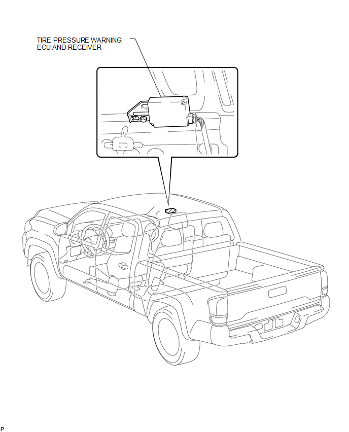
COMPONENTS
ILLUSTRATION
Removal
REMOVAL
PROCEDURE
1. SEPARATE ROOF HEADLINING ASSEMBLY (for Double Cab)
(See page .gif) )
)
2. SEPARATE ROOF HEADLINING ASSEMBLY (for Access Cab)
(See page )
3. REMOVE TIRE PRESSURE WARNING ECU AND RECEIVER
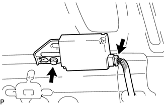
(a) Disconnect the connector.
(b) Remove the bolt and the tire pressure warning ECU and receiver.
Installation
INSTALLATION
PROCEDURE
1. INSTALL TIRE PRESSURE WARNING ECU AND RECEIVER
(a) Install the tire pressure warning ECU and receiver with the nut.
(b) Connect the connector.
2. INSTALL ROOF HEADLINING ASSEMBLY (for Double Cab)
(See page .gif) )
)
3. INSTALL ROOF HEADLINING ASSEMBLY (for Access Cab)
(See page )
4. REGISTRATION TRANSMITTER ID
(See page )
5. PERFORM INITIALIZATION
(See page )
 Precaution
PRECAUTION
1. REMOVAL AND INSTALLATION OF TIRE PRESSURE WARNING VALVE AND TRANSMITTER
(a) When installing a tire, make sure that the tire pressure warning valve and
transmitter does not interfere ...

Other materials:
AUTO LSD Indicator Light does not Come ON
DESCRIPTION
The AUTO LSD does not operate even if the VSC OFF switch is pressed under the
following conditions:
The brake system is faulty.
The temperature inside the hydraulic brake booster increases and the
AUTO LSD operation is suspended.
The rear differential is locked.
...
System Description
SYSTEM DESCRIPTION
1. SEAT BELT WARNING SYSTEM DESCRIPTION
(a) Seat belt warning light operation for driver seat belt:
The seat belt warning light on the combination meter assembly illuminates, blinks
or turns off in accordance with the driver seat belt state, vehicle speed, shift
lever posit ...
Problem Symptoms Table
PROBLEM SYMPTOMS TABLE
HINT:
Use the table below to help determine the cause of problem symptoms.
If multiple suspected areas are listed, the potential causes of the symptoms
are listed in order of probability in the "Suspected Area" column of the
table. Check each sy ...
