Toyota Tacoma (2015-2018) Service Manual: Theft Deterrent System Unexpectedly Sets Itself
DESCRIPTION
A situation in which the theft deterrent system unexpectedly sets itself can be caused when the main body ECU (multiplex network body ECU) cannot detect whether a door is open or closed.
If the theft deterrent system unexpectedly sets itself, there may be a malfunction in a courtesy switch, the main body ECU (multiplex network body ECU) or a wire harness.
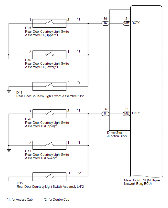
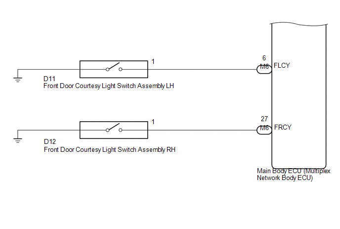
WIRING DIAGRAM
CAUTION / NOTICE / HINT
NOTICE:
- Before replacing the main body ECU (multiplex network body ECU), refer
to Registration (See page
.gif) ).*1
).*1
- *1: w/ Smart Key System
- The theft deterrent system is also set when doors are locked by the auto lock function of the wireless door lock system.
PROCEDURE
|
1. |
CHECK WIRELESS DOOR LOCK SYSTEM OPERATION |
(a) Check that the auto lock function of the wireless door lock system can be canceled.
(1) Unlock the doors using wireless operation or entry operation.
(2) Within 60 seconds, open and close one of the doors.
Result|
Result |
Proceed to |
|---|---|
|
Door locks are locked |
A |
|
Door locks are not locked |
B |
| B | .gif) |
END (SYSTEM NORMAL) |
|
.gif)
|
2. |
READ VALUE USING TECHSTREAM (RR DOOR COURTESY SW, RL DOOR COURTESY SW, BACK DOOR COURTESY SW, FR DOOR COURTESY SW AND FL DOOR COURTESY SW |
(a) Connect the Techstream to the DLC3.
(b) Turn the ignition switch to ON.
(c) Turn the Techstream on.
(d) Enter the following menus: Body Electrical / Main Body / Data List.
(e) Read the Data List according to the display on the Techstream.
Main Body|
Tester Display |
Measurement Item / Range |
Normal Condition |
Diagnostic Note |
|---|---|---|---|
|
RR Door Courtesy SW |
Rear door courtesy light switch assembly RH signal / ON or OFF |
OFF: Rear door RH closed ON: Rear door RH open |
- |
|
RL Door Courtesy SW |
Rear door courtesy light switch assembly LH signal / ON or OFF |
OFF: Rear door LH closed ON: Rear door LH open |
- |
|
FR Door Courtesy SW |
Front door courtesy light switch assembly RH signal / ON or OFF |
OFF: Front door RH closed ON: Front door RH open |
- |
|
FL Door Courtesy SW |
Front door courtesy light switch assembly LH signal / ON or OFF |
OFF: Front door LH closed ON: Front door LH open |
- |
OK:
Normal conditions listed above are displayed.
| OK | |
REPLACE MAIN BODY ECU (MULTIPLEX NETWORK BODY ECU) |
| NG | |
GO TO LIGHTING SYSTEM |
 Theft Deterrent System is not Unset when Engine is Running
DESCRIPTION
The theft deterrent system is unset when the IG signal and engine speed signal
are input to the main body ECU (multiplex network body ECU) for 2 seconds or more
continuously.
The eng ...
 Some Alarm Functions do not Operate
DESCRIPTION
When the alarm sounds, the following alarm functions operate: the roof console
box assembly and No. 1 room light assembly illuminates, and the headlights, taillights
and hazard lights ...
Other materials:
Power Source Circuit
DESCRIPTION
This circuit provides power to operate the forward recognition camera.
WIRING DIAGRAM
CAUTION / NOTICE / HINT
NOTICE:
Inspect the fuses for circuits related to this system before performing the following
inspection procedure.
PROCEDURE
1.
CHECK HARNESS A ...
Dtc Check / Clear
DTC CHECK / CLEAR
CHECK FOR DTC
(a) Connect the Techstream to the DLC3.
(b) Turn the ignition switch to ON.
(c) Turn the Techstream on.
(d) Enter the following menus: Body Electrical / Central Gateway / Trouble Codes.
(e) Read the DTCs.
CLEAR DTC
(a) Connect the Techstream to the DLC3.
(b) ...
Lost Communication with ECM / PCM "A" (U0100,U0125,U0126,U0129)
DESCRIPTION
The millimeter wave radar sensor assembly and ECM communicate with each sensor
and ECU via CAN communication.
If any malfunction is detected in a CAN communication circuit, one or more CAN
communication system DTCs are stored.
DTC No.
Detection Item
...
