Toyota Tacoma (2015-2018) Service Manual: Installation
INSTALLATION
PROCEDURE
1. INSTALL POWER STEERING LINK
(a) Insert the power steering link into the vehicle in the order shown in the illustration.
.png)
.png) |
Install in this Direction (1) |
.png) |
Install in this Direction (2) |
(b) Temporarily install the power steering link with bolt B and nut.
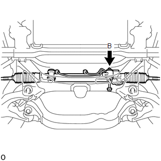
HINT:
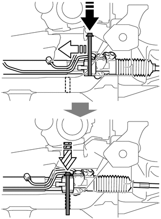
Bolt B cannot be inserted into the power steering link due to interference with the cooler compressor, so slide the power steering link and bolt B together as shown in the illustration, then install bolt B.
|
|
Insert into Power Steering Link |
|
|
Slide |
 |
Insert into Frame |
|
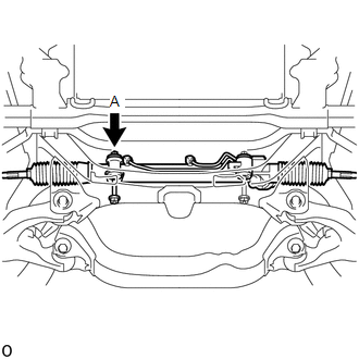
(c) Temporarily install bolt A and nut. |
|
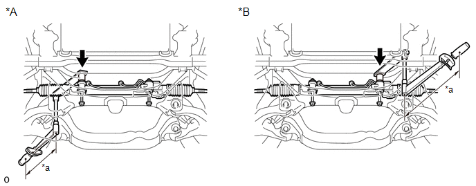
(d) Using SST, tighten the 2 bolts and 2 nuts.
|
*A |
for RH Side |
*B |
for LH Side |
|
*a |
Torque Wrench Fulcrum Length |
- |
- |
SST: 09961-01270
Torque:
Specified tightening torque :
95 N·m {969 kgf·cm, 70 ft·lbf}
NOTICE:
While holding the nut in place, tighten the bolt.
HINT:
- Calculate the torque wrench reading when changing the fulcrum length
of the torque wrench.
Click here
.gif)
- When using SST (fulcrum length of 200 mm (7.87 in.)) + torque wrench (fulcrum length of 380 mm (1.25 ft.)): 62.2 N*m (634 kgf*cm, 46 ft.*lbf)
2. CONNECT PRESSURE FEED TUBE ASSEMBLY
(a) Connect the return hose and slide the clip to secure it.
|
(b) Using a 17 mm union nut wrench, tighten the flare nut and connect the pressure feed tube. Torque: Specified tightening torque : 24 N·m {245 kgf·cm, 18 ft·lbf} NOTICE: Do not damage the pressure feed tube. HINT:
|
|
.png)
(c) Install the tube support bracket with the bolt.
Torque:
28 N·m {286 kgf·cm, 21 ft·lbf}
3. INSTALL TIE ROD END SUB-ASSEMBLY LH
Click here
4. INSTALL TIE ROD END SUB-ASSEMBLY RH
HINT:
Use the same procedure described for the LH side.
5. PLACE FRONT WHEELS FACING STRAIGHT AHEAD
6. INSTALL NO. 2 STEERING INTERMEDIATE SHAFT
|
(a) Align the matchmarks on the No. 2 steering intermediate shaft and power steering link. |
|
.png)
(b) Install the No. 2 steering intermediate shaft to the power steering link with bolt C.
Torque:
35 N·m {357 kgf·cm, 26 ft·lbf}
|
(c) Align the matchmarks on the steering intermediate shaft and steering sliding yoke. |
|
.png)
(d) Install the steering sliding yoke to the steering intermediate shaft and slide it upward.
(e) Align the matchmarks on the steering sliding yoke and No. 2 steering intermediate shaft.
(f) Install the steering sliding yoke to the No. 2 steering intermediate shaft with bolts A and B.
Torque:
35 N·m {357 kgf·cm, 26 ft·lbf}
7. INSTALL FRONT DIFFERENTIAL CARRIER ASSEMBLY (for 4WD)
Click here
8. INSTALL OIL PAN COVER SILENCER
Click here
9. INSTALL NO. 1 ENGINE UNDER COVER SUB-ASSEMBLY
Torque:
30 N·m {306 kgf·cm, 22 ft·lbf}
10. INSTALL FRONT WHEELS
Torque:
113 N·m {1152 kgf·cm, 83 ft·lbf}
11. INSPECT STEERING WHEEL CENTER POINT
12. ADD POWER STEERING FLUID
13. BLEED POWER STEERING FLUID
Click here
14. INSPECT FOR POWER STEERING FLUID LEAK
15. INSPECT AND ADJUST FRONT WHEEL ALIGNMENT
Click here
 Inspection
INSPECTION
PROCEDURE
1. INSPECT TIE ROD END SUB-ASSEMBLY
(a) Flip the ball joint stud back and forth 5 times as shown in the illustration
before installing the nut.
(b) Using a torque wrench, ...

Other materials:
ABS Warning Light Remains ON
DESCRIPTION
If any of the following is detected, the ABS warning light remains on.
The skid control ECU (master cylinder solenoid) connectors are disconnected
from the skid control ECU (master cylinder solenoid).
There is a malfunction in the skid control ECU (master cylinder soleno ...
ECU Power Source Circuit
WIRING DIAGRAM
CAUTION / NOTICE / HINT
NOTICE:
Inspect the fuses for circuits related to this system before performing the following
inspection procedure.
PROCEDURE
1.
INSPECT BATTERY
(a) Check the battery voltage.
Standard voltage:
11 to 14 V
NG
...
Event data recorder
This vehicle is equipped with an event data recorder (EDR). The main purpose
of an EDR is to record, in certain crash or near crash-like situations, such as
an air bag deployment or hitting a road obstacle, data that will assist in understanding
how a vehicle’s systems performed. The EDR is ...
