Toyota Tacoma (2015-2018) Service Manual: Theft Deterrent System is not Unset when Engine is Running
DESCRIPTION
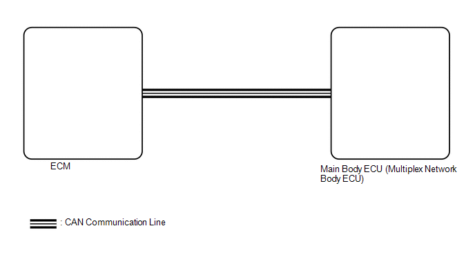
The theft deterrent system is unset when the IG signal and engine speed signal are input to the main body ECU (multiplex network body ECU) for 2 seconds or more continuously.
The engine speed signal is sent from the ECM to the main body ECU (multiplex network body ECU). For this reason, if there is an abnormality in an ECU or wire harness, the system may not function correctly.
WIRING DIAGRAM
CAUTION / NOTICE / HINT
NOTICE:
- Before replacing the main body ECU (multiplex network body ECU), refer
to Registration (See page
.gif) ).*1
).*1
- *1: w/ Smart Key System
- Inspect the fuses for circuits related to this system before performing the following procedure.
PROCEDURE
|
1. |
REPLACE MAIN BODY ECU (MULTIPLEX NETWORK BODY ECU) |
(a) Replace the main body ECU (multiplex network body ECU) with a new one (See
page ).
| NEXT | .gif) |
END |
 Theft Deterrent System cannot be Set or Unset
DESCRIPTION
When the ignition switch is turned off and all doors and the engine hood are
closed, the theft deterrent system is set when doors are locked by wireless operation*1,
key linked operat ...
 Theft Deterrent System Unexpectedly Sets Itself
DESCRIPTION
A situation in which the theft deterrent system unexpectedly sets itself can
be caused when the main body ECU (multiplex network body ECU) cannot detect whether
a door is open or clos ...
Other materials:
Rear Speed Sensor RH Performance (C1411,C1412)
DESCRIPTION
Refer to DTCs C1401 and C1402 (See page ).
DTC Code
DTC Detection Condition
Trouble Area
C1411
C1412
One of the following conditions is met:
When the vehicle is driven in reverse at a speed of 3 km/h (2
...
Rear Door(for Access Cab)
Adjustment
ADJUSTMENT
CAUTION / NOTICE / HINT
HINT:
Use the same procedures for both the LH and RH sides.
The procedure described below is for the LH side.
Centering bolts are used to mount the door hinge to the vehicle body
and door. The door cannot be adjusted with the ce ...
Crawl Indicator Light Remains ON
DESCRIPTION
When CRAWL starts after operating the CRAWL switch (drive monitor switch), the
CRAWL indicator light turns on. While CRAWL is in the process of stopping, the CRAWL
indicator light begins blinking. When CRAWL totally stops, the CRAWL indicator light
turns off.
WIRING DIAGRAM
CA ...
