Toyota Tacoma (2015-2018) Service Manual: Sound Signal Circuit between Radio Receiver and Stereo Jack Adapter
DESCRIPTION
The No. 1 stereo jack adapter assembly sends the sound signal from an external device to the radio and display receiver assembly via this circuit.
If there is an open or short in the circuit, sound cannot be heard from the speakers even if there is no malfunction in the radio and display receiver assembly, or speakers.
WIRING DIAGRAM
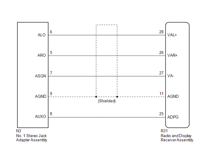
PROCEDURE
|
1. |
CHECK HARNESS AND CONNECTOR (RADIO AND DISPLAY RECEIVER ASSEMBLY - NO. 1 STEREO JACK ADAPTER ASSEMBLY) |
(a) Disconnect the R31 radio and display receiver assembly connector.
(b) Disconnect the N3 No. 1 stereo jack adapter assembly connector.
(c) Measure the resistance according to the value(s) in the table below.
Standard Resistance:
|
Tester Connection |
Condition |
Specified Condition |
|---|---|---|
|
R31-25 (ADPG) - N3-8 (AUXO) |
Always |
Below 1 Ω |
|
R31-26 (VAR+) - N3-5 (ARO) |
Always |
Below 1 Ω |
|
R31-28 (VAL+) - N3-6 (ALO) |
Always |
Below 1 Ω |
|
R31-27 (VA-) - N3-7 (ASGN) |
Always |
Below 1 Ω |
|
R31-11 (AGND) - N3-9 (AGND) |
Always |
Below 1 Ω |
|
R31-25 (ADPG) - Body ground |
Always |
10 kΩ or higher |
|
R31-26 (VAR+) - Body ground |
Always |
10 kΩ or higher |
|
R31-28 (VAL+) - Body ground |
Always |
10 kΩ or higher |
|
R31-27 (VA-) - Body ground |
Always |
10 kΩ or higher |
|
R31-11 (AGND) - Body ground |
Always |
10 kΩ or higher |
| OK | .gif) |
PROCEED TO NEXT SUSPECTED AREA SHOWN IN PROBLEM SYMPTOMS TABLE |
| NG | |
REPAIR OR REPLACE HARNESS OR CONNECTOR |
 Speaker Circuit
DESCRIPTION
If there is a short in a speaker circuit, the radio and display receiver
assembly detects it and stops output to the speakers.
Thus sound cannot be heard from the speakers ...
 Data Signal Circuit between Radio Receiver and Stereo Jack Adapter
DESCRIPTION
The No. 1 stereo jack adapter assembly sends the sound data signal or image data
signal from a USB device to the radio and display receiver assembly via this circuit.
WIRING DIAGRAM
...
Other materials:
Front Radar Sensor Incorrect Axial Gap (C1A11,C1A14)
DESCRIPTION
When the system determines that the vehicle is driving straight ahead based on
signals from the yaw rate and acceleration sensor (airbag sensor assembly), etc.,
the millimeter wave radar sensor assembly performs self-diagnosis to check if the
sensor beam axis is misaligned.
C1A11 ...
Pressure Sensor or Switch (C1254)
DESCRIPTION
The accumulator pressure sensor is connected to the skid control ECU in the master
cylinder solenoid.
DTC No.
DTC Detecting Condition
Trouble Areas
C1254
Accumulator pressure sensor fault
(Fluid pressure does not chang ...
Fail-safe Chart
FAIL-SAFE CHART
If any of the following DTCs are stored, the ECM enters fail-safe mode to allow
the vehicle to be driven temporarily.
DTC
Fail-safe Operation
Fail-safe Deactivation Condition
P161A87
Generator command is maintained
...
