Toyota Tacoma (2015-2018) Service Manual: Terminals Of Ecu
TERMINALS OF ECU
1. CHECK DRIVER SIDE JUNCTION BLOCK AND MAIN BODY ECU (MULTIPLEX NETWORK BODY ECU)
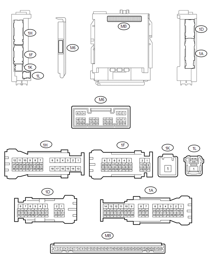
(a) Disconnect the MB main body ECU (multiplex network body ECU) connectors.
(b) Measure the voltage and resistance according to the value(s) in the table below.
HINT:
Measure the values on the wire harness side with the connectors disconnected.
|
Tester Connection |
Wiring Color |
Terminal Description |
Condition |
Specified Condition |
|---|---|---|---|---|
|
MB-11(GND1) - Body ground |
- |
Ground |
Always |
Below 1 Ω |
|
MB-31 (BECU) - Body ground |
- |
Battery power supply |
Always |
11 to 14 V |
|
MB-30 (ACC) - Body ground |
- |
ACC power supply |
Ignition switch ACC |
11 to 14 V |
|
MB-30 (ACC) - Body ground |
- |
ACC power supply |
Ignition switch off |
Below 1 V |
|
MB-32 (IG) - Body ground |
- |
IG power supply |
Ignition switch ON |
11 to 14 V |
|
MB-32 (IG) - Body ground |
- |
IG power supply |
Ignition switch off |
Below 1 V |
If the result is not as specified, there may be a malfunction in the wire harness.
(c) Reconnect the MB main body ECU (multiplex network body ECU) connectors.
(d) Measure the voltage and check for pulses according to the value(s) in the table below.
|
Tester Connection |
Wiring Color |
Terminal Description |
Condition |
Specified Condition |
|---|---|---|---|---|
|
1H-10 (ACT-) - Body ground |
LA-G - Body ground |
Door lock motor unlock drive output (except driver door) |
Door control switch or driver door key cylinder off |
Below 1 V |
|
Door control switch or driver door key cylinder unlocked |
11 to 14 V |
|||
|
1D-3 (ACT-) - Body ground |
G - Body ground |
Door lock motor unlock drive output (except driver door) |
Door control switch or driver door key cylinder off |
Below 1 V |
|
Door control switch or driver door key cylinder unlocked |
11 to 14 V |
|||
|
1D-1 (ACT+) - Body ground |
R - Body ground |
Door lock motor lock drive output (all doors) |
Door control switch or driver door key cylinder off |
Below 1 V |
|
Door control switch or driver door key cylinder locked |
11 to 14 V |
|||
|
1H-12 (ACT+) - Body ground |
LA-R - Body ground |
Door lock motor lock drive output (all doors) |
Door control switch or driver door key cylinder off |
Below 1 V |
|
Door control switch or driver door key cylinder locked |
11 to 14 V |
|||
|
1D-2 (ACTD) - Body ground |
B - Body ground |
Driver door lock motor unlock drive output |
Door control switch or driver door key cylinder off |
Below 1 V |
|
Door control switch or driver door key cylinder unlocked |
11 to 14 V |
|||
|
M6-2 (UL3) - Body ground |
G - Body ground |
Driver door key-linked unlock input |
Driver door key cylinder turned to neutral position → on (unlock) |
Pulse generation → Below 1 V |
|
M6-29 (L2) - Body ground |
SB - Body ground |
Driver door key-linked lock input |
Driver door key cylinder turned to neutral position → on (lock) |
Pulse generation → Below 1 V |
|
M6-27 (FRCY) - Body ground |
LG - Body ground |
Front door courtesy light switch RH input |
Front door RH open |
Below 1 V |
|
M6-27 (FRCY) - Body ground |
LG - Body ground |
Front door courtesy light switch RH input |
Front door RH open |
11 to 14 V |
|
M6-6 (FLCY) - Body ground |
Y - Body ground |
Front door courtesy light switch LH input |
Front door LH open |
Below 1 V |
|
M6-6 (FLCY) - Body ground |
Y - Body ground |
Front door courtesy light switch LH input |
Front door LH closed |
11 to 14 V |
|
1H-36 (LCTY) - Body ground |
P - Body ground |
Rear door courtesy light switch LH input*1 Upper access panel lock assembly LH input*2 Lower access panel lock assembly LH input*2 |
Rear door LH open |
Below 1 V |
|
1H-36 (LCTY) - Body ground |
P - Body ground |
Rear door courtesy light switch LH input*1 Upper access panel lock assembly LH input*2 Lower access panel lock assembly LH input*2 |
Rear door LH closed |
Pulse generation |
|
1D-30 (RCTY) - Body ground |
V - Body ground |
Rear door courtesy light switch RH input*1 Upper access panel lock assembly RH input*2 Lower access panel lock assembly RH input*2 |
Rear door RH open |
Below 1 V |
|
1D-30 (RCTY) - Body ground |
V - Body ground |
Rear door courtesy light switch RH input*1 Upper access panel lock assembly RH input*2 Lower access panel lock assembly RH input*2 |
Rear door RH closed |
Pulse generation |
|
1D-11 (LSFL) - Body ground |
P - Body ground |
Front door LH unlock detection switch input |
Front door LH unlocked |
Below 1 V |
|
1D-11 (LSFL) - Body ground |
P - Body ground |
Front door LH unlock detection switch input |
Ignition switch off, all doors closed and front door LH locked |
Pulse generation |
|
1D-24 (LSFR) - Body ground |
GR - Body ground |
Front door RH unlock detection switch input |
Front door RH unlocked |
Below 1 V |
|
1D-24 (LSFR) - Body ground |
GR - Body ground |
Front door RH unlock detection switch input |
Ignition switch off, all doors closed and front door RH locked |
Pulse generation |
|
1A-41 (LSR) - Body ground |
Y - Body ground |
Rear door RH unlock detection switch input |
Rear door RH or LH unlocked |
Below 1 V |
|
1A-41 (LSR) - Body ground |
Y - Body ground |
Rear door RH unlock detection switch input |
Ignition switch off, all doors closed and rear door RH and LH locked |
Pulse generation |
|
1H-27 (LSR) - Body ground |
L - Body ground |
Rear door LH unlock detection switch input |
Rear door LH or RH unlocked |
Below 1 V |
|
1H-27 (LSR) - Body ground |
L - Body ground |
Rear door LH unlock detection switch input |
Ignition switch off, all doors closed and rear door LH and RH locked |
Pulse generation |
|
1F-29 (BZR) - Body ground |
Y - Body ground |
Wireless door lock buzzer signal |
Wireless door lock buzzer off |
Below 1 V |
|
1F-29 (BZR) - Body ground |
Y - Body ground |
Wireless door lock buzzer signal |
Wireless door lock buzzer on |
Pulse generation |
|
31-1D (KSW) - Body ground*5 |
G - Body ground |
Key unlock warning switch input |
Key in ignition key cylinder |
Below 1 V |
|
No key in ignition key cylinder |
11 to 14 V or Pulse generation |
- *1: for Double Cab
- *2: for Access Cab
- *3: w/ Jam Protection
- *4: w/o Jam Protection
- *5: w/o Smart Key System
 Problem Symptoms Table
PROBLEM SYMPTOMS TABLE
Use the table below to help determine the cause of problem symptoms.
If multiple suspected areas are listed, the potential causes of the symptoms
are listed in o ...
 All Doors LOCK/UNLOCK Functions do not Operate Via Door Control Switch or Door
Key Cylinder
All Doors LOCK/UNLOCK Functions do not Operate Via Door Control Switch or Door
Key Cylinder
DESCRIPTION
The main body ECU (multiplex network body ECU) receives switch signals from the
power window regulator master switch assembly and driver door key cylinder lock
or unlock switch signal ...
Other materials:
Main Body ECU Vehicle Information Reading/Writing Process Malfunction (B15F6)
DESCRIPTION
This DTC is stored when items controlled by the main body ECU (multiplex network
body ECU) cannot be customized via the audio and visual system vehicle customization
screen.
HINT:
The main body ECU (multiplex network body ECU) controls the items for the following
systems th ...
Precaution
PRECAUTION
1. PRECAUTIONS WHEN USING TECHSTREAM
(a) When using the Techstream to troubleshoot the engine immobiliser system:
Connect the Techstream to the DLC3 while the ignition switch is off, and turn
a door courtesy light switch on and off at 1.5-second intervals until communication
betwee ...
Headlight switch
The headlights can be operated manually.
Turning the end of the lever turns on the lights as follows:
Type A
The daytime running lights turn
on.
The side marker, parking, tail,
license plate, daytime running lights and instrument panel lights turn on.
The headlights and all lights lis ...
