Toyota Tacoma (2015-2018) Service Manual: Noise Filter(for 2gr-fks)
Components
COMPONENTS
ILLUSTRATION
Removal
REMOVAL
PROCEDURE
1. DISCONNECT CABLE FROM NEGATIVE BATTERY TERMINAL
2. REMOVE V-BANK COVER
(See page .gif) )
)
3. REMOVE AIR CLEANER ASSEMBLY
(See page )
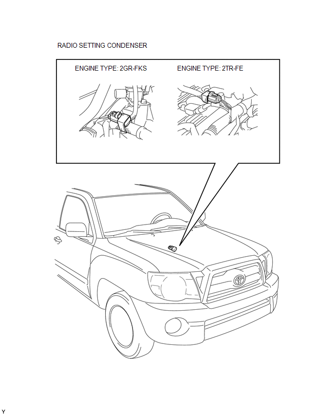
4. REMOVE RADIO SETTING CONDENSER
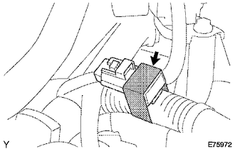
(a) Disconnect the connector.
(b) Remove the tape and the radio setting condenser.
Installation
INSTALLATION
PROCEDURE
1. INSTALL RADIO SETTING CONDENSER
.png)
(a) Connect the connector.
(b) Wind new vinyl tape around the hose and install the radio setting condenser.
2. INSTALL AIR CLEANER ASSEMBLY
(See page .gif) )
)
3. INSTALL V-BANK COVER
(See page )
4. CONNECT CABLE TO NEGATIVE BATTERY TERMINAL
Torque:
5.4 N·m {55 kgf·cm, 48 in·lbf}
 Microphone Amplifier
Components
COMPONENTS
ILLUSTRATION
*A
w/o Sliding Roof
*B
w/ Sliding Roof
*1
TELEPHONE MICROPHONE ASSEMBLY
-
...
 Noise Filter(for 2tr-fe)
Components
COMPONENTS
ILLUSTRATION
Removal
REMOVAL
PROCEDURE
1. DISCONNECT CABLE FROM NEGATIVE BATTERY TERMINAL
2. REMOVE AIR CLEANER ASSEMBLY
(See page )
3. REMOVE RADIO SETTING COND ...
Other materials:
Theft Deterrent System Unexpectedly Sets Itself
DESCRIPTION
A situation in which the theft deterrent system unexpectedly sets itself can
be caused when the main body ECU (multiplex network body ECU) cannot detect whether
a door is open or closed.
If the theft deterrent system unexpectedly sets itself, there may be a malfunction
in a court ...
Some Alarm Functions do not Operate
DESCRIPTION
When the alarm sounds, the following alarm functions operate: the roof console
box assembly and No. 1 room light assembly illuminates, and the headlights, taillights
and hazard lights flash, and the security horn and vehicle horn sound intermittently.
WIRING DIAGRAM
CAUTION / ...
Data List / Active Test
DATA LIST / ACTIVE TEST
1. READ DATA LIST
HINT:
Using the Techstream to read the Data List allows the values or states of switches,
sensors, actuators and other items to be read without removing any parts. This non-intrusive
inspection can be very useful because intermittent conditions or sig ...
