Toyota Tacoma (2015-2018) Service Manual: Terminals Of Ecm
TERMINALS OF ECM
HINT:
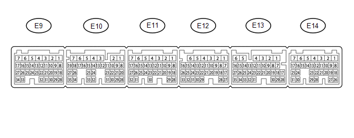
The standard normal voltage between each pair of ECM terminals is shown in the table below. The appropriate conditions for checking each pair of terminals are also indicated. The result of checks should be compared with the standard normal voltage for that pair of terminals, displayed in the Specified Condition column. The illustration above can be used as a reference to identify the ECM terminal locations.
|
Terminal No. (Symbol) |
Wiring Color |
Terminal Description |
Condition |
Specified Condition |
|---|---|---|---|---|
|
E14-2 (BATT) - E11-1 (E1) |
L - W-B |
Battery (for measuring battery voltage and for ECM memory) |
Always |
11 to 14 V |
|
E12-6 (+BM) - E11-1 (E1) |
GR - W-B |
Power source of throttle actuator |
Always |
11 to 14 V |
|
E14-3 (+B) - E11-1 (E1) |
B - W-B |
Power source of ECM |
Ignition switch ON |
11 to 14 V |
|
E14-4 (+B2) - E11-1 (E1) |
B - W-B |
Power source of ECM |
Ignition switch ON |
11 to 14 V |
|
E14-25 (MREL) - E11-1 (E1) |
GR - W-B |
EFI-MAIN NO. 1 relay operation signal |
Ignition switch ON |
11 to 14 V |
|
E9-26 (VCNE) - E11-1 (E1) |
R - W-B |
Power source of crankshaft position sensor (specific voltage) |
Ignition switch ON |
4.5 to 5.5 V |
|
E9-25 (NE+) - E9-33 (NE-) |
B - G |
Crankshaft position sensor |
Idling |
Pulse generation |
|
E13-24 (SPD) - E11-1 (E1) |
R - W-B |
Vehicle speed signal from combination meter assembly |
Driving at 20 km/h (12 mph) |
Pulse generation |
|
E11-1 (E1) - Body ground |
W-B - Body ground |
Ground circuit of ECM |
Always |
Below 1 Ω |
 Diagnosis System
DIAGNOSIS SYSTEM
1. DESCRIPTION
(a) To check DTCs, connect the Techstream to the Data Link Connector 3 (DLC3)
of the vehicle. The Techstream displays DTCs and freeze frame data. The DTCs and
fre ...
 Check Mode Procedure
CHECK MODE PROCEDURE
1. DESCRIPTION
Check mode has a higher sensitivity to malfunctions and can detect malfunctions
that cannot be detected in normal mode. Check mode can also detect all of the ma ...
Other materials:
Automatic Light Control Sensor
Components
COMPONENTS
ILLUSTRATION
Installation
INSTALLATION
PROCEDURE
1. INSTALL AUTOMATIC LIGHT CONTROL SENSOR
(a) Engage the 2 claws to install the automatic light control sensor.
2. INSTALL NO. 2 INSTRUMENT PANEL SPEAKER PANEL SUB-ASSEMBLY
(See page )
On-vehicle Inspection
ON ...
Installation
INSTALLATION
CAUTION / NOTICE / HINT
CAUTION:
Some of these service operations affect the SRS airbag system. Read
the precautionary notices concerning the SRS airbag system before servicing
(See page ).
If the side airbag was deployed, replace the front seat assembly with
...
Engine
General Maintenance
GENERAL MAINTENANCE
CAUTION / NOTICE / HINT
HINT:
Inspect these items when the engine is cold.
PROCEDURE
1. REPLACE CHAIN SUB-ASSEMBLY
HINT:
2TR-FE: See page
2GR-FKS: See page
2. INSPECT DRIVE BELT
HINT:
2TR-FE: See page
2GR-FKS: ...
