Toyota Tacoma (2015-2018) Service Manual: Diagnosis System
DIAGNOSIS SYSTEM
1. DESCRIPTION
(a) To check DTCs, connect the Techstream to the Data Link Connector 3 (DLC3)
of the vehicle. The Techstream displays DTCs and freeze frame data. The DTCs and
freeze frame data can be cleared with the Techstream (See page
.gif) ).
).
2. NORMAL MODE AND CHECK MODE
(a) The diagnosis system operates in "normal mode" during normal vehicle use. In normal mode, "2 trip detection logic" is used to ensure accurate detection of malfunctions. "Check mode" is also available to technicians as an option. In check mode, "1 trip detection logic" is used for simulating malfunction symptoms and increasing the system's ability to detect malfunctions, including intermittent malfunctions.
3. 2 TRIP DETECTION LOGIC
(a) When a malfunction is first detected, the malfunction is stored as a pending DTC in the ECM memory (1st trip). If the same malfunction is detected during the next drive cycle, the DTC is stored (2nd trip).
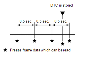
4. FREEZE FRAME DATA
(a) The Techstream records freeze frame data in 5 different instances: 1) 3 times before the DTC is stored, 2) once when the DTC is stored, and 3) once after the DTC is stored. These sets of data can be used to simulate the vehicle condition around the time when the malfunction occurred. The data may help in finding the cause of the malfunction, or in judging if the DTC was caused by a temporary malfunction.
5. CHECK DATA LINK CONNECTOR 3 (DLC3)
(a) Check the DLC3 (See page ).
 Problem Symptoms Table
PROBLEM SYMPTOMS TABLE
Use the table below to help determine the cause of problem symptoms. If multiple
suspected areas are listed, the potential causes of the symptoms are listed in order
of pro ...
 Terminals Of Ecm
TERMINALS OF ECM
HINT:
The standard normal voltage between each pair of ECM terminals is shown in the
table below. The appropriate conditions for checking each pair of terminals are
also indic ...
Other materials:
System Description
SYSTEM DESCRIPTION
1. GENERAL
(a) This system uses ultrasonic sensors to detect any obstacles at the corners
and the rear of the vehicle. The system then informs the driver of the distance
between the sensors and an obstacle as well as their positions by indicating them
on the multi-informat ...
Precaution
PRECAUTION
CAUTION:
The vehicle is equipped with SRS, which consists of a driver airbag,
front passenger airbag, side airbags and curtain shield airbags and knee
airbags. Failure to carry out service operations in the correct sequence
could cause the SRS to unexpectedly deploy ...
Installation
INSTALLATION
PROCEDURE
1. INSTALL STEERING COLUMN ASSEMBLY
(a) Install the steering column assembly with the 2 nuts and bolt.
Torque:
21 N·m {214 kgf·cm, 15 ft·lbf}
(b) Connect each of the connectors to the steering column assembly.
(c) Connect the wire harness clamps to the steering colu ...
