Toyota Tacoma (2015-2018) Service Manual: System Diagram
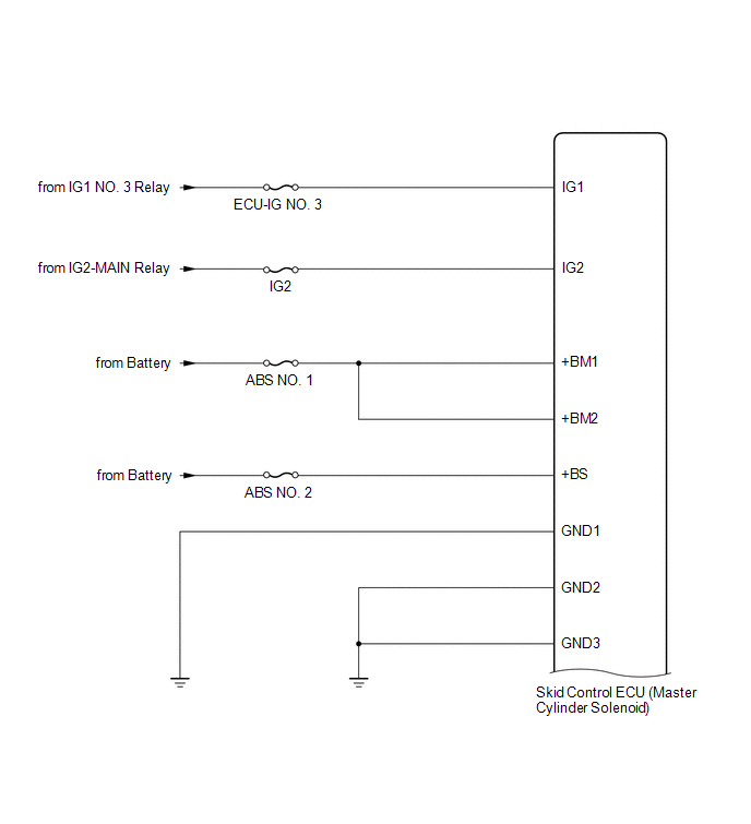
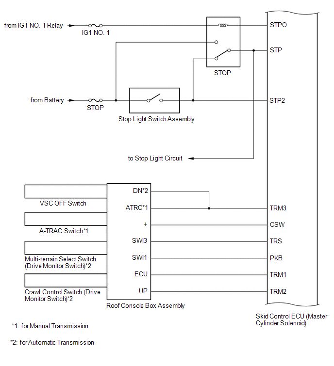
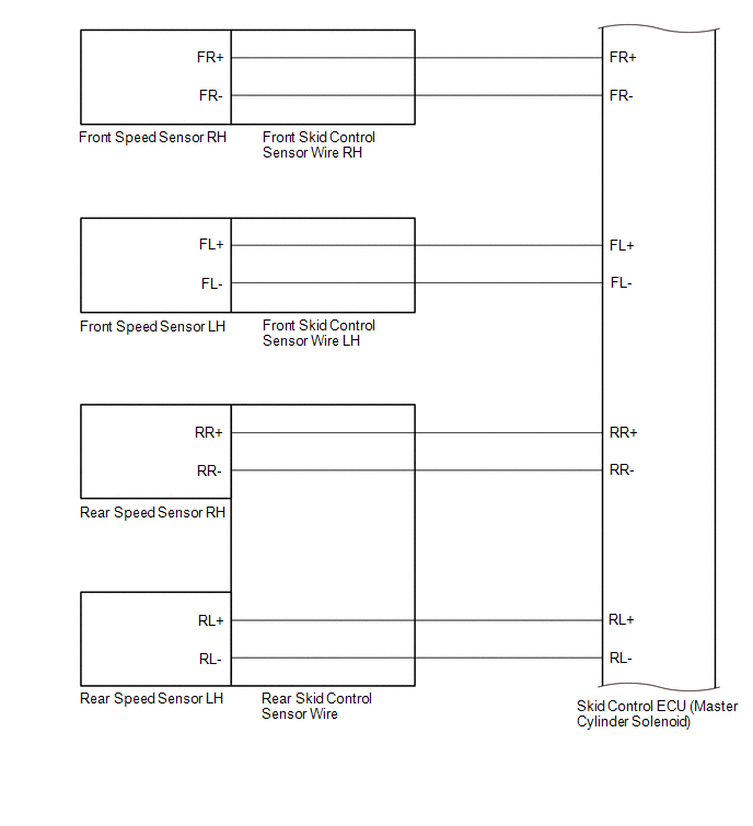
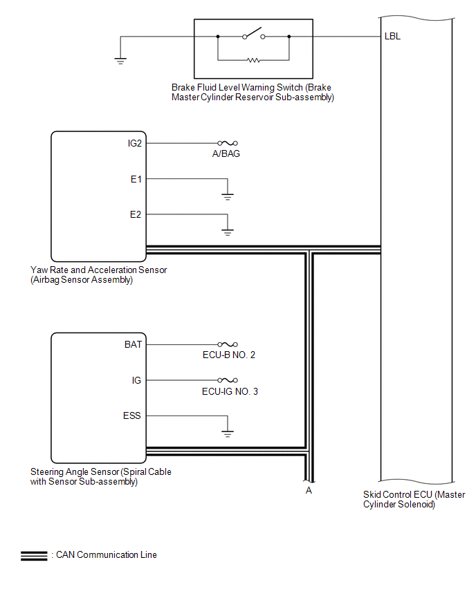
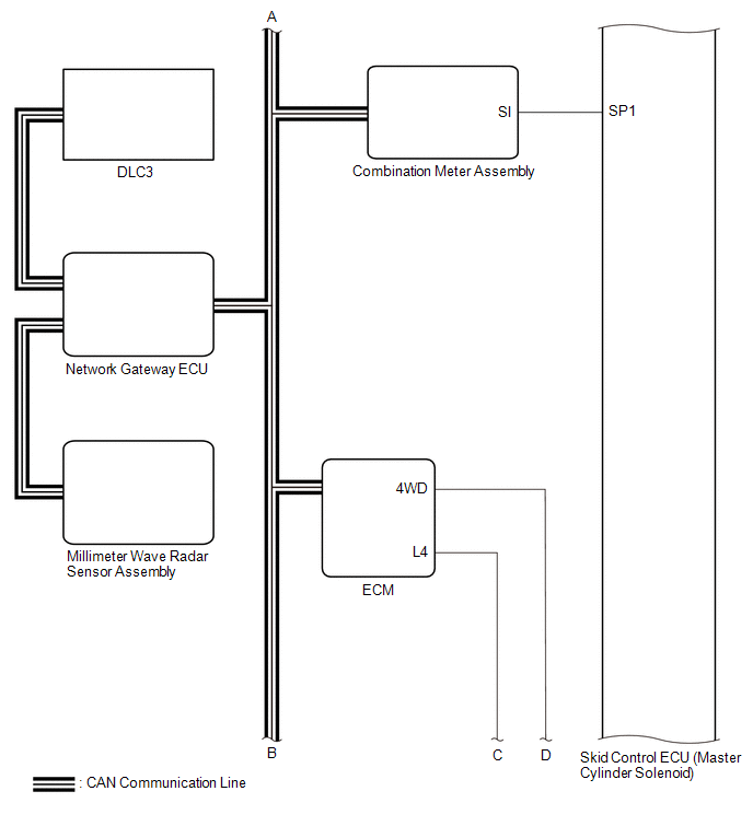
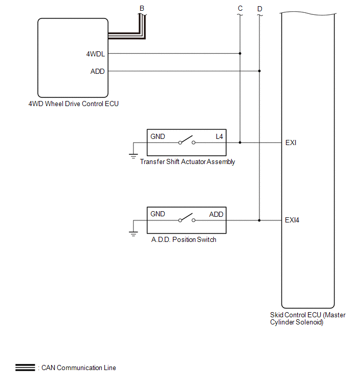
SYSTEM DIAGRAM
|
Transmitting ECU (Transmitter) |
Receiving ECU |
Signals |
Communication Method |
|---|---|---|---|
|
ECM |
Skid control ECU |
|
CAN communication system |
|
Yaw rate and acceleration sensor (Airbag sensor assembly) |
Skid control ECU |
Yaw rate and acceleration signal |
CAN communication system |
|
Steering angle sensor (spiral cable with sensor sub-assembly) |
Skid control ECU |
Steering angle signal |
CAN communication system |
|
Skid control ECU |
ECM |
Throttle opening angle request signal |
CAN communication system |
|
Skid control ECU |
Combination meter assembly |
|
CAN communication system |
|
4 wheel drive control ECU (for 4WD or w/ Rear Differential Lock) |
Skid control ECU |
|
CAN communication system |
 System Description
SYSTEM DESCRIPTION
1. SYSTEM DESCRIPTION
HINT:
The skid control ECU is built into the hydraulic brake booster.
(a) ABS (Anti-lock Brake System)
The ABS helps prevent the wheels from locking when ...
 Check For Intermittent Problems
CHECK FOR INTERMITTENT PROBLEMS
1. DESCRIPTION
HINT:
A momentary interruption (open circuit) in the connectors and/or wire harness
between the sensors and ECUs can be detected through the ECU dat ...
Other materials:
AV Signal Stoppage (Low Battery Voltage) (B158F)
DESCRIPTION
This DTC is stored when a video or audio signal is interrupted due to battery
voltage input to the radio and display receiver assembly dropping temporarily.
DTC Code
DTC Detection Condition
Trouble Area
B158F
A video or aud ...
Parking Brake Switch Circuit
DESCRIPTION
This circuit is from the parking brake switch assembly to the navigation receiver
assembly.
WIRING DIAGRAM
PROCEDURE
1.
CHECK VEHICLE SIGNAL (OPERATION CHECK)
(a) Display the "Vehicle Signal Check Mode" screen (See page
). ...
New Key cannot be Registered
DESCRIPTION
If an electrical key transmitter could not be newly registered, wave interference
or a malfunction of the certification ECU (smart key ECU assembly), electrical key
transmitter sub-assembly, steering lock ECU (steering lock actuator or UPR bracket
assembly) or electrical key and T ...
