Toyota Tacoma (2015-2018) Service Manual: Check Mode Procedure
CHECK MODE PROCEDURE
1. DESCRIPTION
Check mode has a higher sensitivity to malfunctions and can detect malfunctions that cannot be detected in normal mode. Check mode can also detect all of the malfunctions that can be detected in normal mode. In check mode, DTCs are stored with 1 trip detection logic.
NOTICE:
- All DTCs and freeze frame data will be cleared if: 1) the Techstream is used to change the ECM from normal mode to check mode or vice versa; or 2) during check mode, the ignition switch is turned from ON to ACC or off.
- Before changing to check mode, make a note of the DTCs and freeze frame data.
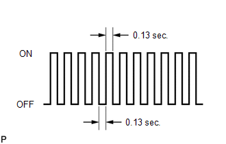
2. CHECK MODE PROCEDURE
(a) Make sure that the following conditions are met:
(1) Battery voltage is 11 V or higher.
(2) The throttle valve is fully closed.
(3) The shift lever is in neutral.
(4) The A/C switch is off.
(b) Connect the Techstream to the DLC3.
(c) Turn the ignition switch to ON.
(d) Turn the Techstream on.
(e) Enter the following menus: Powertrain / Transmission / Utility / Check Mode.
(f) Check that the MIL flashes as shown in the illustration.
(g) Start the engine. The MIL should turn off after the engine starts.
(h) Simulate the conditions of the malfunction described by the customer.
(i) Using the Techstream, check for DTCs and freeze frame data.
 Terminals Of Ecm
TERMINALS OF ECM
HINT:
The standard normal voltage between each pair of ECM terminals is shown in the
table below. The appropriate conditions for checking each pair of terminals are
also indic ...
 Data List / Active Test
DATA LIST / ACTIVE TEST
1. DATA LIST
NOTICE:
In the table below, the values listed under "Normal Condition" are reference
values. Do not depend solely on these reference values when dec ...
Other materials:
Diagnostic Trouble Code Chart
DIAGNOSTIC TROUBLE CODE CHART
Power Window Control System
DTC Code
Detection Item
See page
B2311
Power Window Motor Malfunction
B2312
Power Window Switch Malfunction
...
Anti-glare inside rear view mirror
Glare from the headlights of vehicles behind can be reduced by using the following
functions.
Manual anti-glare inside rear view
mirror
Normal position
Anti-glare position
Auto anti-glare inside rear view
mirror (type A)
In automatic mode, sensors are used to detect the headlights of ...
On-vehicle Inspection
ON-VEHICLE INSPECTION
PROCEDURE
1. CHECK STEERING WHEEL FREE PLAY
(a) Stop the vehicle and align the tires facing straight ahead.
(b) Gently turn the steering wheel right and left by hand, and check
the steering wheel free play.
Maximum free play:
30 mm (1.18 in.)
Text i ...
