Toyota Tacoma (2015-2018) Service Manual: TC and CG Terminal Circuit
DESCRIPTION
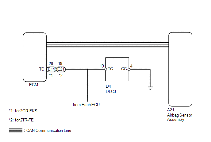
DTC output mode is set by connecting terminals TC and CG of the DLC3.
The DTCs are displayed by blinking the SRS warning light.
HINT:
- Make sure that DTCs which relate to the CAN communication system are
not output. If any of these DTCs are output, check the CAN communication
system (See page
.gif) ).
). - The DTC output mode signal is transmitted through the CAN to an ECU including the airbag sensor assembly. Thus if no systems enter DTC output mode, the ECM may have a malfunction.
- When a warning light keeps blinking, a short to ground in the wiring of terminal TC of the DLC3 or an internal ground short in each ECU is suspected.
WIRING DIAGRAM
PROCEDURE
|
1. |
CHECK HARNESS AND CONNECTOR (DLC3 - ECM) |
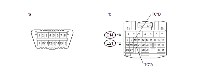 Text in Illustration
|
*A |
for 2GR-FKS |
*B |
for 2TR-FE |
|
*a |
DLC3 |
*b |
Front view of wire harness connector (to ECM) |
(a) Turn the ignition switch off.
(b) Disconnect the connector from the ECM.
(c) Measure the resistance according to the value(s) in the table below.
Standard Resistance:
for 2GR-FKS|
Tester Connection |
Condition |
Specified Condition |
|---|---|---|
|
D4-13 (TC) - E14-20 (TC) |
Always |
Below 1 Ω |
|
Tester Connection |
Condition |
Specified Condition |
|---|---|---|
|
D4-13 (TC) - E21-19 (TC) |
Always |
Below 1 Ω |
| NG | .gif) |
REPAIR OR REPLACE HARNESS, ECU OR CONNECTOR |
|
.gif)
|
2. |
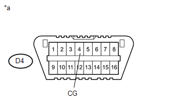
CHECK HARNESS AND CONNECTOR (CG OF DLC3 - BODY GROUND) |
|
(a) Measure the resistance according to the value(s) in the table below. Standard Resistance:
|
|
| NG | |
REPAIR OR REPLACE HARNESS, ECU OR CONNECTOR |
|
|
3. |
CHECK HARNESS AND CONNECTOR (TC CIRCUIT OF ECM) |
(a) Measure the resistance according to the value(s) in the table below.
Standard Resistance:
for 2GR-FKS|
Tester Connection |
Condition |
Specified Condition |
|---|---|---|
|
E14-20 (TC) - Body ground |
Always |
1 MΩ or higher |
|
Tester Connection |
Condition |
Specified Condition |
|---|---|---|
|
E21-19 (TC) - Body ground |
Always |
1 MΩ or higher |
| NG | |
REPAIR OR REPLACE HARNESS, ECU OR CONNECTOR |
|
|
4. |
CHECK DTC |
SST: 09843-18040
|
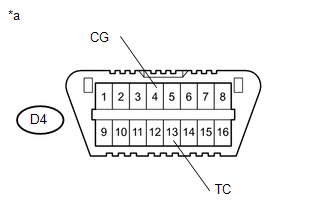
(a) Using SST, connect terminals TC and CG of the DLC3. NOTICE: Connect the terminals to the correct positions to avoid a malfunction. Text in Illustration
|
|
| A | |
USE SIMULATION METHOD TO CHECK |
| B | |
REPLACE ECM |
| C | |
REPLACE ECM |
| D | |
REPLACE AIRBAG SENSOR ASSEMBLY |
 SRS Warning Light Remains ON
DESCRIPTION
The SRS warning light is located on the combination meter assembly.
When the SRS condition is normal, the SRS warning light illuminates for approximately
6 seconds after the ignition s ...
 Center Airbag Sensor Assembly
Components
COMPONENTS
ILLUSTRATION
On-vehicle Inspection
ON-VEHICLE INSPECTION
PROCEDURE
1. INSPECT AIRBAG SENSOR ASSEMBLY (for Vehicle not Involved in Collision)
(a) Perform a diagnostic ...
Other materials:
Removal
REMOVAL
CAUTION / NOTICE / HINT
NOTICE:
Release the vacuum from booster by depressing the brake pedal several times.
Then remove the brake master cylinder from brake booster.
PROCEDURE
1. PRECAUTION
NOTICE:
After turning the ignition switch off, waiting time may be required before disconnect ...
Transfer Shift Motor Control Circuit Circuit Open (P17A8)
DESCRIPTION
This DTC is output when an open circuit in the transfer shift motor drive circuit
is detected.
DTC No.
Detection Item
DTC Detection Condition
Trouble Area
P17A8
Transfer Shift Motor Control Circuit Circuit Open
...
Navigation Receiver
Components
COMPONENTS
ILLUSTRATION
ILLUSTRATION
Removal
REMOVAL
PROCEDURE
1. REMOVE INSTRUMENT CLUSTER CENTER FINISH PANEL SUB-ASSEMBLY
(See page )
2. REMOVE NAVIGATION RECEIVER ASSEMBLY WITH BRACKET
(a) Remove the 4 bolts.
(b ...
