Toyota Tacoma (2015-2018) Service Manual: SRS Warning Light Remains ON
DESCRIPTION
The SRS warning light is located on the combination meter assembly.
When the SRS condition is normal, the SRS warning light illuminates for approximately 6 seconds after the ignition switch is turned from off to ON, and then turns off automatically.
If there is a malfunction in the SRS, the SRS warning light illuminates or blinks to inform the driver of the problem. When terminals TC and CG of the DLC3 are connected, the SRS warning light blinks to indicate DTCs.
The airbag sensor assembly is equipped with a voltage-increase circuit (DC-DC converter) in case the source voltage decreases. When the battery voltage decreases, the voltage-increase circuit (DC-DC converter) boosts the SRS voltage up to the normal level.
Malfunctions relating to battery voltage decreases cause the SRS warning light to illuminate. However, no DTCs are recorded in the airbag sensor assembly. The SRS warning light turns off automatically when the source voltage returns to normal.
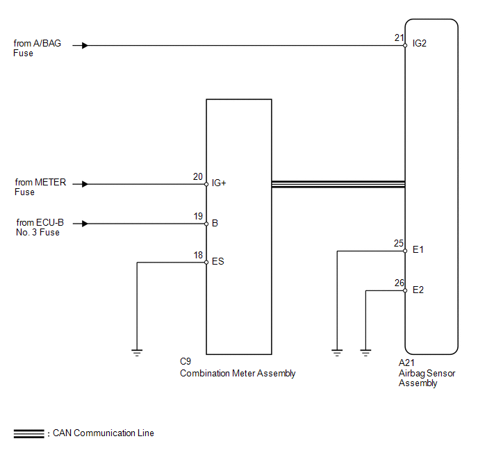
WIRING DIAGRAM
CAUTION / NOTICE / HINT
NOTICE:
- Inspect the fuses for circuits related to this system before performing the following inspection procedure.
- After turning the ignition switch off, waiting time may be required
before disconnecting the cable from the battery terminal. Therefore, make
sure to read the disconnecting the cable from the battery terminal notice
before proceeding with work (See page
.gif) ).
).
PROCEDURE
|
1. |
CHECK FOR DTC (CAN COMMUNICATION SYSTEM) |
(a) Turn the ignition switch to ON.
(b) Check the DTCs (See page ).
OK:
DTC is not output.
| NG | .gif) |
GO TO CAN COMMUNICATION SYSTEM |
|
.gif)
|
2. |
INSPECT BATTERY |
(a) Measure the voltage of the battery.
Standard Voltage:
|
Tester Connection |
Condition |
Specified Condition |
|---|---|---|
|
Battery |
Always |
11 to 14 V |
| NG | |
CHECK AND REPLACE BATTERY OR CHARGING SYSTEM |
|
|
3. |
CHECK CONNECTION OF CONNECTORS |
(a) Turn the ignition switch off.
(b) Disconnect the cable from the negative (-) battery terminal, and wait for at least 90 seconds.
(c) Check that the connectors are properly connected to the airbag sensor assembly and combination meter assembly.
OK:
The connectors are properly connected.
| NG | |
CONNECT CONNECTORS PROPERLY |
|
|
4. |
CHECK HARNESS AND CONNECTOR (SOURCE VOLTAGE OF AIRBAG SENSOR ASSEMBLY) |
|
(a) Disconnect the connector from the airbag sensor assembly. |
|
(b) Connect the cable to the negative (-) battery terminal, and wait for at least 2 seconds.
(c) Turn the ignition switch to ON.
(d) Operate all components of the electrical system (defogger, wipers, headlights, heater blower, etc.).
(e) Measure the voltage according to the value(s) in the table below.
Standard Voltage:
|
Tester Connection |
Switch Condition |
Specified Condition |
|---|---|---|
|
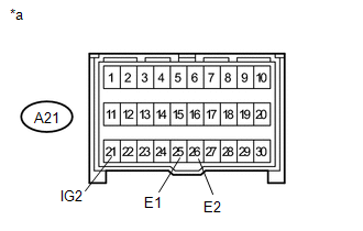
A21-21 (IG2) - A21-25 (E1) |
Ignition switch ON |
11 to 14 V |
|
A21-21 (IG2) - A21-26 (E2) |
Ignition switch ON |
11 to 14 V |
|
*a |
Front view of wire harness connector (to Airbag Sensor Assembly) |
| NG | |
REPLACE HARNESS AND CONNECTOR |
|
|
5. |
CHECK HARNESS AND CONNECTOR (SOURCE VOLTAGE OF COMBINATION METER ASSEMBLY) |
|
(a) Disconnect the cable from the negative (-) battery terminal, and wait for at least 90 seconds. |
|
(b) Disconnect the connector from the combination meter assembly.
(c) Connect the cable to the negative (-) battery terminal, and wait for at least 2 seconds.
(d) Turn the ignition switch to ON.
(e) Measure the voltage according to the value(s) in the table below.
Standard Voltage:
|
Tester Connection |
Switch Condition |
Specified Condition |
|---|---|---|
|
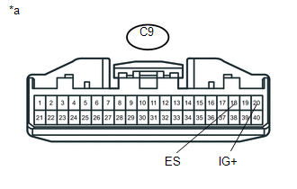
C9-20 (IG+) - C9-18 (ES) |
Ignition switch ON |
11 to 14 V |
|
*a |
Front view of wire harness connector (to Combination Meter Assembly) |
| NG | |
REPAIR OR REPLACE HARNESS OR CONNECTOR |
|
|
6. |
CHECK SRS WARNING LIGHT |
(a) Turn the ignition switch off.
(b) Disconnect the cable from the negative (-) battery terminal, and wait for at least 90 seconds.
(c) Connect the connector to the combination meter assembly.
(d) Connect the cable to the negative (-) battery terminal, and wait for at least 2 seconds.
(e) Turn the ignition switch to ON.
(f) Check the SRS warning light condition.
OK:
The SRS warning light turns off after the primary check period and comes on again after approximately 10 seconds.
HINT:
The primary check period lasts for approximately 6 seconds after the ignition switch is turned to ON.
| OK | |
REPLACE AIRBAG SENSOR ASSEMBLY |
| NG | |
REPLACE COMBINATION METER ASSEMBLY |
 SRS Warning Light does not Come ON
DESCRIPTION
See page .
WIRING DIAGRAM
See page .
CAUTION / NOTICE / HINT
NOTICE:
Inspect the fuses for circuits related to this system before performing
the following inspection pr ...
 TC and CG Terminal Circuit
DESCRIPTION
DTC output mode is set by connecting terminals TC and CG of the DLC3.
The DTCs are displayed by blinking the SRS warning light.
HINT:
Make sure that DTCs which relate to the CA ...
Other materials:
Operation Check
OPERATION CHECK
1. CHECK AUTO OPERATION
NOTICE:
Make sure that initialization has been completed before inspection (See
page ).
The sliding roof auto operation can be customized. Make sure that the
auto operation is ON (See page ).
HINT:
When pressing the switch for ...
Disassembly
DISASSEMBLY
PROCEDURE
1. INSPECT FRONT PROPELLER SHAFT UNIVERSAL JOINT SPIDER BEARING
(a) Check the spider bearings for wear and damage.
(b) Check each spider bearing's axial play by turning the yoke while holding
the shaft tightly.
Maximum bearing axial play:
0 to 0.05 mm (0 to 0.002 i ...
Installation
INSTALLATION
PROCEDURE
1. INSTALL FUEL SUCTION TUBE SET GASKET
(a) Ensure gasket groove is clean and free of foreign particles.
(b) Install a new gasket onto the fuel tank.
(c) Make sure that the gasket sits in the groove.
2. INSTALL FUEL SU ...
