Toyota Tacoma (2015-2018) Service Manual: Removal
REMOVAL
PROCEDURE
1. REMOVE FUEL DELIVERY PIPE ASSEMBLY LH (FUEL PRESSURE SENSOR)
(See page .gif) )
)
NOTICE:
- Do not remove the fuel pressure sensor from the fuel delivery pipe sub-assembly LH.
- If a fuel pressure sensor is removed, replace the fuel delivery pipe sub-assembly LH (fuel pressure sensor) with a new one.
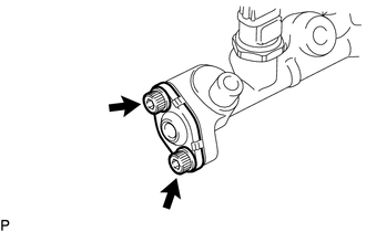
2. REMOVE FUEL PIPE PLUG SUB-ASSEMBLY
(a) Secure the fuel delivery pipe assembly LH in a vise between aluminum plates.
NOTICE:
Do not overtighten the vise.
(b) Remove the dust cap sub-assembly from the fuel pipe plug sub-assembly.
|
(c) Using a 5 mm hexagon wrench, remove the 2 bolts and fuel pipe plug sub-assembly. |
|
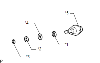
(d) Remove the gasket from the fuel pipe plug sub-assembly.
|
(e) Remove the O-ring, No. 3 fuel injector back-up ring, No. 2 fuel injector back-up ring and No. 1 fuel injector back-up ring from the fuel pipe plug sub-assembly. Text in Illustration
|
|
(f) Remove the fuel delivery pipe assembly LH from the vise.
 Components
COMPONENTS
ILLUSTRATION
...
 Inspection
INSPECTION
PROCEDURE
1. INSPECT FUEL DELIVERY PIPE SUB-ASSEMBLY LH (FUEL PRESSURE SENSOR)
NOTICE:
Do not remove the fuel pressure sensor from the fuel delivery pipe sub-assembly
LH.
...
Other materials:
Adjustment
ADJUSTMENT
PROCEDURE
1. REMOVE FRONT CONSOLE BOX
(See page )
2. ADJUST TRANSMISSION CONTROL CABLE ASSEMBLY
(a) Move the shift lever to N.
(b) Disconnect the end of the transmission control cable assembly from the transmission
floor shift assembly.
Text in Illustration
...
Check Bus 5 Lines for Short Circuit
DESCRIPTION
There may be a short circuit between the CAN main bus lines and/or CAN branch
lines when the resistance between terminals 15 (CA5H) and 16 (CA5L) of the central
gateway ECU (network gateway ECU) is below 54 Ω.
Detection Item
Trouble Area
Resi ...
Problem Symptoms Table
PROBLEM SYMPTOMS TABLE
HINT:
Use the table below to help determine the cause of problem symptoms.
If multiple suspected areas are listed, the potential causes of the symptoms
are listed in order of probability in the "Suspected Area" column of the
table. Check each sy ...
