Toyota Tacoma (2015-2018) Service Manual: Center Airbag Sensor Assembly
Components
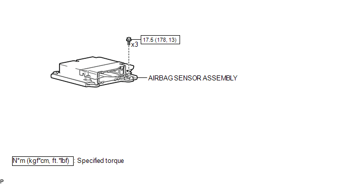
COMPONENTS
ILLUSTRATION
On-vehicle Inspection
ON-VEHICLE INSPECTION
PROCEDURE
1. INSPECT AIRBAG SENSOR ASSEMBLY (for Vehicle not Involved in Collision)
(a) Perform a diagnostic system check (See page
.gif) ).
).
2. INSPECT AIRBAG SENSOR ASSEMBLY (for Vehicle Involved in Collision and Airbag has not Deployed)
(a) Perform a diagnostic system check (See page
).
3. INSPECT AIRBAG SENSOR ASSEMBLY (for Vehicle Involved in Collision and Airbag has Deployed)
(a) Replace the airbag sensor assembly.
CAUTION:
For removal and installation procedures of the airbag sensor assembly, be sure to follow the correct procedure.
HINT:
The airbag sensor assembly should be replaced after any of the airbags has deployed, as it has been subjected to the impact.
Removal
REMOVAL
PROCEDURE
1. PRECAUTION
CAUTION:
Be sure to read Precaution thoroughly before servicing (See page
.gif) ).
).
NOTICE:
After turning the ignition switch off, waiting time may be required before disconnecting the cable from the negative (-) battery terminal. Therefore, make sure to read the disconnecting the cable from the negative (-) battery terminal notices before proceeding with work.
Click here
2. DISCONNECT CABLE FROM NEGATIVE BATTERY TERMINAL
CAUTION:
Wait at least 90 seconds after disconnecting the cable from the negative (-) battery terminal to prevent airbag and seat belt pretensioner activation.
NOTICE:
When disconnecting the cable, some systems need to be initialized after the cable is reconnected.
Click here
3. REMOVE FRONT CONSOLE BOX
Click here
4. REMOVE AIRBAG SENSOR ASSEMBLY
(a) Check that the ignition switch is OFF.
(b) Check that the cable is disconnected from the battery negative (-) terminal.
CAUTION:
Wait at least 90 seconds after disconnecting the cable from the negative (-) battery terminal to prevent airbag and seat belt pretensioner activation.
|
(c) Pull the lever down to disconnect the connector holder. |
|
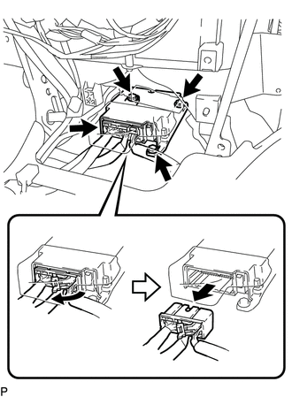
(d) Remove the 3 bolts and airbag sensor assembly.
Installation
INSTALLATION
PROCEDURE
1. INSTALL AIRBAG SENSOR ASSEMBLY
(a) Check that the ignition switch is OFF.
(b) Check that the cable is disconnected from the battery negative (-) terminal.
CAUTION:
Wait at least 90 seconds after disconnecting the cable from the negative (-) battery terminal to prevent airbag and seat belt pretensioner activation.
(c) Install the airbag sensor assembly with the 3 bolts.
Torque:
17.5 N·m {178 kgf·cm, 13 ft·lbf}
NOTICE:
- If the airbag sensor assembly has been dropped, or there are any cracks, dents or other defects in the case, bracket or connector, replace it with a new one.
- When installing the airbag sensor assembly, be careful that the SRS wiring does not interfere with other parts and that it is not pinched between other parts.
(d) Check that there is no looseness in the installation parts of the airbag sensor assembly.
|
(e) Connect the connector holder to lock the lever. Text in Illustration
NOTICE: Confirm that the lever is locked. |
|
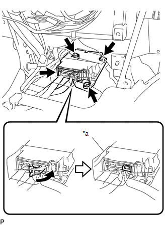
(f) Check that the waterproof sheet is properly set.
2. INSTALL FRONT CONSOLE BOX
Click here .gif)
3. CONNECT CABLE TO NEGATIVE BATTERY TERMINAL
Torque:
5.4 N·m {55 kgf·cm, 48 in·lbf}
NOTICE:
When disconnecting the cable, some systems need to be initialized after the cable is reconnected.
Click here
4. INSPECT SRS WARNING LIGHT
Click here
 TC and CG Terminal Circuit
DESCRIPTION
DTC output mode is set by connecting terminals TC and CG of the DLC3.
The DTCs are displayed by blinking the SRS warning light.
HINT:
Make sure that DTCs which relate to the CA ...

Other materials:
Speed Signal Malfunction (B15C2)
DESCRIPTION
The navigation receiver assembly receives a vehicle speed signal from the combination
meter assembly and information from the navigation antenna assembly, and then adjusts
the vehicle position.
The navigation receiver assembly stores this DTC when the difference between
the speed ...
Diagnosis System
DIAGNOSIS SYSTEM
DIAGNOSIS FUNCTION
(a) The diagnosis function turns off the cruise control indicator, illuminates
the master warning light and displays a warning message when a malfunction is detected.
When a malfunction is detected in the dynamic radar cruise control system, DTCs
are store ...
Removal
REMOVAL
PROCEDURE
1. PRECAUTION
NOTICE:
After turning the ignition switch off, waiting time may be required before disconnecting
the cable from the battery terminal. Therefore, make sure to read the disconnecting
the cable from the battery terminal notice before proceeding with work.
Click ...
