Toyota Tacoma (2015-2018) Service Manual: TC and CG Terminal Circuit
DESCRIPTION
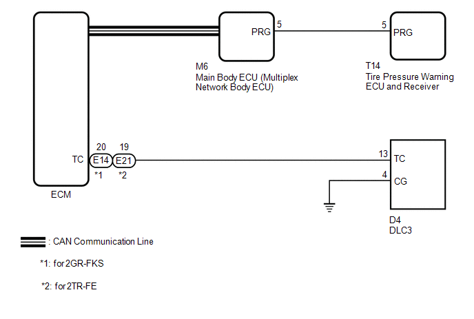
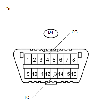
Tire pressure warning system DTCs can be checked by connecting terminals 13 (TC) and 4 (CG) of the DLC3. The DTCs are indicated by blinking the tire pressure warning light.
WIRING DIAGRAM
PROCEDURE
|
1. |
CHECK CAN COMMUNICATION SYSTEM |
(a) Check for DTCs (See page .gif) ).
).
|
Result |
Proceed to |
|---|---|
|
DTCs are not output. |
A |
|
DTCs are output. |
B |
| B | .gif) |
GO TO CAN COMMUNICATION SYSTEM |
|
.gif)
|
2. |
CHECK DTC (C2179/79) |
(a) Check if DTC C2179/79 is output (See page
).
|
Result |
Proceed to |
|---|---|
|
DTC C2179/79 is not output. |
A |
|
DTC C2179/79 is output. |
B |
| B | |
GO TO DTC (C2179/79) |
|
|
3. |
INSPECT DLC3 |
|
(a) Turn the ignition switch to ON. Text in Illustration
|
|
(b) Measure the voltage according to the value(s) in the table below.
Standard Voltage:
|
Tester Connection |
Switch Condition |
Specified Condition |
|---|---|---|
|
D4-13 (TC) - D4-4 (CG) |
Ignition switch ON |
11 to 14 V |
| NG | |
GO TO STEP 5 |
|
|
4. |
REPLACE ECM |
|
(a) Turn the ignition switch off. Text in Illustration
|
|
(b) Replace the ECM.
for 2GR-FKS: (See page
)
for 2TR-FE: (See page
)
(c) Using SST, connect terminals TC and CG of the DLC3.
SST: 09843-18040
(d) Check that the tire pressure warning light is blinking.
OK:
The tire pressure warning light is blinking.
HINT:
If troubleshooting has been carried out according to Problem Symptoms Table,
refer back to the table and proceed to the next step before replacing the part (See
page ).
| OK | |
END |
| NG | |
PROCEED TO NEXT SUSPECTED AREA SHOWN IN PROBLEM SYMPTOMS TABLE |
|
5. |
CHECK HARNESS AND CONNECTOR (TC of DLC3 - ECM) |
(a) Disconnect the A43 ECM connector.
(b) Measure the resistance according to the value(s) in the table below.
Standard Resistance:
for 2GR-FKS:|
Tester Connection |
Condition |
Specified Condition |
|---|---|---|
|
D4-13 (TC) - E14-20 (TC) |
Always |
Below 1 Ω |
|
D4-13 (TC) or E14-20 (TC) - Body ground |
Always |
10 kΩ or higher |
Standard Resistance:
for 2TR-FE:|
Tester Connection |
Condition |
Specified Condition |
|---|---|---|
|
D4-13 (TC) - E21-19 (TC) |
Always |
Below 1 Ω |
|
D4-13 (TC) or E21-19 (TC) - Body ground |
Always |
10 kΩ or higher |
| NG | |
REPAIR OR REPLACE HARNESS OR CONNECTOR |
|
|
6. |
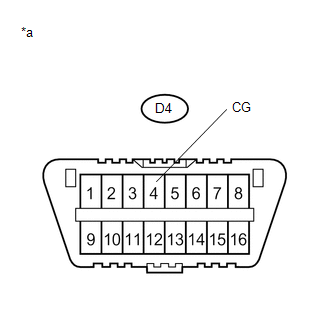
CHECK HARNESS AND CONNECTOR (CG of DLC3 - BODY GROUND) |
|
(a) Measure the resistance according to the value(s) in the table below. Standard Resistance:
HINT: If troubleshooting has been carried out according to Problem Symptoms
Table, refer back to the table and proceed to the next step before replacing
the part (See page |
|
| NG | |
REPAIR OR REPLACE HARNESS OR CONNECTOR |
|
|
7. |
REPLACE ECM |
|
(a) Replace the ECM. for 2GR-FKS: (See page for 2TR-FE: (See page
|
|
(b) Using SST, connect terminals TC and CG of the DLC3.
SST: 09843-18040
(c) Check that the tire pressure warning light is blinking.
OK:
The tire pressure warning light is blinking.
HINT:
If troubleshooting has been carried out according to Problem Symptoms Table,
refer back to the table and proceed to the next step before replacing the part (See
page ).
| OK | |
END |
| NG | |
PROCEED TO NEXT SUSPECTED AREA SHOWN IN PROBLEM SYMPTOMS TABLE |
 ECU Power Source Circuit
DESCRIPTION
The IG circuit is the power source for the tire pressure warning ECU and receiver.
WIRING DIAGRAM
CAUTION / NOTICE / HINT
NOTICE:
When replacing the tire pressure warning EC ...
 Tire Pressure Warning Light Circuit
DESCRIPTION
If the tire pressure warning ECU and receiver detects any problems, the tire
pressure warning light blinks for 1 minute then illuminates, and tire pressure monitoring
is disabled at t ...
Other materials:
Mechanical System Tests
MECHANICAL SYSTEM TESTS
1. STALL SPEED TEST
HINT:
This test is to check the overall performance of the engine and transmission.
CAUTION:
This test should be done on a paved surface (a surface that is not slippery).
To ensure safety, perform this test in an open and level area tha ...
Front Crankshaft Oil Seal
Components
COMPONENTS
ILLUSTRATION
Installation
INSTALLATION
PROCEDURE
1. INSTALL TIMING GEAR CASE OR TIMING CHAIN CASE OIL SEAL
(a) Apply MP grease to the lip of a new timing gear case or timing chain case
oil seal.
(b) Using SST and a hammer, tap in the timing gear case ...
Reassembly
REASSEMBLY
PROCEDURE
1. INSTALL FRONT LOWER ARM BUSH NO. 1
(a) Install a new lower arm bush using SST, a press and steel plate.
SST: 09631-12090
SST: 09631-32020
NOTICE:
Push the lower arm bush in until the bush positioning protrusions come to the
positions shown in the illustration.
2. ...
