Toyota Tacoma (2015-2018) Service Manual: Tire Pressure Warning Light Circuit
DESCRIPTION
If the tire pressure warning ECU and receiver detects any problems, the tire pressure warning light blinks for 1 minute then illuminates, and tire pressure monitoring is disabled at the same time. At this time, the ECU stores a DTC in memory.
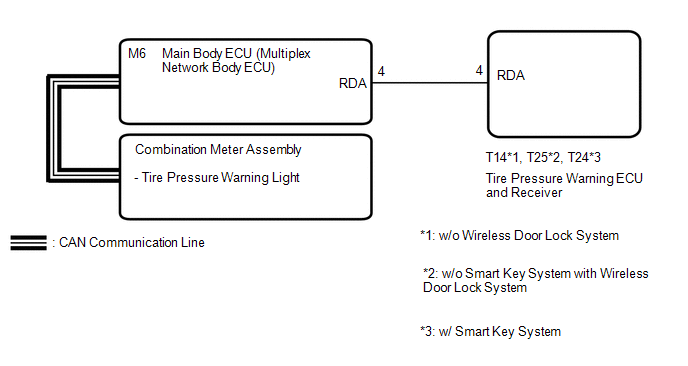
Connecting terminals TC and CG of the DLC3 makes the tire pressure warning light blink to output DTCs. The tire pressure warning ECU and receiver sends the tire pressure warning light illumination request signal to the main body ECU (multiplex network body ECU) via a direct line. The main body ECU (multiplex network body ECU) then sends the signal to the combination meter assembly via CAN communication.
WIRING DIAGRAM
CAUTION / NOTICE / HINT
NOTICE:
- When replacing the tire pressure warning ECU and receiver, read the transmitter IDs stored in the old ECU using the Techstream and write them down before removal.
- It is necessary to perform initialization (See page
.gif) ) after registration (See page
) of the transmitter IDs into the tire
pressure warning ECU and receiver if the ECU has been replaced.
) after registration (See page
) of the transmitter IDs into the tire
pressure warning ECU and receiver if the ECU has been replaced.
PROCEDURE
|
1. |
CHECK FOR DTC (CAN COMMUNICATION SYSTEM) |
(a) Check if CAN communication system DTCs are output (See page
).
|
Result |
Proceed to |
|---|---|
|
DTCs are not output. |
A |
|
DTCs are output. |
B |
| B | .gif) |
GO TO CAN COMMUNICATION SYSTEM |
|
.gif)
|
2. |
CHECK DTC OUTPUT (B1247) |
(a) Clear the DTCs (See page ).
(b) Turn the ignition switch off.
(c) Turn the ignition switch to ON.
(d) Check for DTCs (See page ).
OK:
DTC B1247 is not output.
| NG | |
GO TO DTC (B1247) |
|
|
3. |
CHECK OPERATION OF TIRE PRESSURE WARNING LIGHT (ACTIVETEST) |
(a) Turn the ignition switch off.
(b) Connect the Techstream to the DLC3.
(c) Turn the ignition switch to ON.
(d) Turn the Techstream on.
(e) Enter the following menus: Body Electrical / Combination Meter / Active Test.
(f) Check the condition of the tire pressure warning light using the Techstream.
Combination Meter|
Tester Display |
Measurement Item |
Control Range |
Diagnostic Note |
|---|---|---|---|
|
Indicat. Tire Pressure Warning System |
Tire pressure warning light |
OFF or ON |
Confirm that the vehicle is stopped with the engine idling. |
OK:
The tire pressure warning light turns on or off in accordance with the Techstream operation.
| OK | |
REPLACE TIRE PRESSURE WARNING ECU AND RECEIVER |
| NG | |
GO TO METER / GAUGE SYSTEM |
 TC and CG Terminal Circuit
DESCRIPTION
Tire pressure warning system DTCs can be checked by connecting terminals 13 (TC)
and 4 (CG) of the DLC3. The DTCs are indicated by blinking the tire pressure warning
light.
WIRING DI ...
 Tire Position Not Identified
DESCRIPTION
The tire pressure warning ECU and receiver identifies the tire position for each
tire pressure warning valve and transmitter according to the wheel speed signals
from the skid control ...
Other materials:
Room Oscillator does not Recognize Key
DESCRIPTION
If code verification cannot be performed in the vehicle interior, there may be
problems with the communication between the vehicle (indoor electrical key antenna
assembly (front floor) or (rear floor)) and electrical key transmitter sub-assembly,
or the certification ECU (smart ke ...
Confirm Cellular Phone Functionality
PROCEDURE
1.
CHECK CUSTOMER'S CELLULAR PHONE COMPATIBILITY
(a) Check if the cellular phone is compatible (Refer to http://www.toyota.com/entune/).
Result
Result
Proceed to
Cellular phone is compatible
A
...
Manual Shifting Test
MANUAL SHIFTING TEST
1. PERFORM MANUAL SHIFTING TEST
HINT:
Using this test, it can be determined whether a problem is in an electrical
circuit or if it is a mechanical problem in the transmission.
If any abnormalities are found in the following test, the problem is
in the tran ...
