Toyota Tacoma (2015-2018) Service Manual: Installation
INSTALLATION
CAUTION / NOTICE / HINT
HINT:
Perform "Inspection After Repairs" after replacing the fuel delivery pipe assembly
LH (fuel pressure sensor) (See page .gif) ).
).
PROCEDURE
1. INSTALL FUEL PIPE PLUG SUB-ASSEMBLY
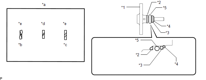
(a) Install a new O-ring, new No. 1 fuel injector back-up ring, new No. 2 fuel injector back-up ring and new No. 3 fuel injector back-up ring to the fuel pipe plug sub-assembly as shown in the illustration.
 Text in Illustration
|
*1 |
Fuel Pipe Plug Sub-assembly |
*2 |
No. 1 Fuel Injector Back-up Ring |
|
*3 |
No. 3 Fuel Injector Back-up Ring |
*4 |
No. 3 Fuel Injector Back-up Ring |
|
*5 |
O-ring |
- |
- |
|
*a |
Opening |
*b |
Overlapping |
|
*c |
Stretched |
*d |
Correct |
|
*e |
Incorrect |
- |
- |
NOTICE:
- Check that there is no foreign matter or damage on the O-ring groove of the fuel pipe plug sub-assembly.
- Check that the No. 1 fuel injector back-up ring and No. 3 fuel injector back-up ring are installed in the correct orientation.
- Make sure that the No. 1 fuel injector back-up ring, No. 2 fuel injector back-up ring, No. 3 fuel injector back-up ring and O-ring are installed in the correct order.
- Check that the alignment of the No. 1 fuel injector back-up ring is not overlapped or stretched as shown in the illustration.
- After installing the O-ring, check that it is not contaminated with foreign matter and is not damaged.
(b) Secure the fuel delivery pipe assembly LH in a vise between aluminum plates.
NOTICE:
Do not overtighten the vise.
|
(c) Install a new gasket to the fuel pipe plug sub-assembly as shown in the illustration. |
|
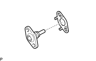
(d) Using a 5 mm hexagon wrench, install the fuel pipe plug sub-assembly to the fuel delivery pipe assembly LH with the 2 bolts.
Torque:
10 N·m {102 kgf·cm, 7 ft·lbf}
(e) Install a new dust cap sub-assembly to the fuel pipe plug sub-assembly.
2. INSTALL FUEL DELIVERY PIPE ASSEMBLY LH (FUEL PRESSURE SENSOR)
(See page )
NOTICE:
- Do not remove the fuel pressure sensor from the fuel delivery pipe sub-assembly LH.
- If a fuel pressure sensor is removed, replace the fuel delivery pipe sub-assembly LH (fuel pressure sensor) with a new one.
HINT:
Perform "Inspection After Repairs" after replacing the fuel delivery pipe assembly
LH (fuel pressure sensor) (See page ).
 Inspection
INSPECTION
PROCEDURE
1. INSPECT FUEL DELIVERY PIPE SUB-ASSEMBLY LH (FUEL PRESSURE SENSOR)
NOTICE:
Do not remove the fuel pressure sensor from the fuel delivery pipe sub-assembly
LH.
...
 Fuel Pump
...
Other materials:
Diagnosis System
DIAGNOSIS SYSTEM
CHECK DLC3
(a) Check the DLC3.
Click here
FUNCTION OF WARNING INDICATOR AND MESSAGE
(a) If the lane departure alert system is not functioning properly, the driver
is warned by the lane departure alert indicator and multi-information display warning
message on the combinat ...
Symbols used in illustrations
The symbol of a circle with a slash
through it means “Do not”, “Do not do this”, or “Do not let this happen”.
Arrows indicating operations
Indicates the action (pushing, turning,
etc.) used to operate switches and other devices.
Indicates the outcome of an operation
(e.g. a ...
Passenger Side Buckle Switch Circuit Malfunction (B1771)
DESCRIPTION
The passenger side buckle switch circuit consists of the occupant detection ECU
and the front seat inner belt assembly RH.
DTC B1771 is recorded when a malfunction is detected in the passenger side buckle
switch circuit.
Troubleshoot DTC B1771 first when DTCs B1771 and B1795 are o ...
