Toyota Tacoma (2015-2018) Service Manual: ECU Power Source Circuit
DESCRIPTION
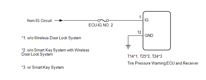
The IG circuit is the power source for the tire pressure warning ECU and receiver.
WIRING DIAGRAM
CAUTION / NOTICE / HINT
NOTICE:
- When replacing the tire pressure warning ECU and receiver, read the transmitter IDs stored in the old ECU using the Techstream and write them down before removal.
- It is necessary to perform initialization (See page
.gif) ) after registration (See page
) of the transmitter IDs into the tire
pressure warning ECU and receiver if the ECU has been replaced.
) after registration (See page
) of the transmitter IDs into the tire
pressure warning ECU and receiver if the ECU has been replaced.
HINT:
Inspect the fuses for circuits related to this system before performing the following procedure.
PROCEDURE
|
1. |
CHECK HARNESS AND CONNECTOR (ECU - BATTERY AND BODYGROUND) |
|
(a) Disconnect the T14*1, T25*2, T24*3 tire pressure warning ECU and receiver connector. |
|
.png)
(b) Measure the voltage according to the value(s) in the table below.
Standard Voltage:
|
Tester Connection |
Switch Condition |
Specified Condition |
|---|---|---|
|
T14-1 (IG) - Body ground*1 T25-1 (IG) - Body ground*2 T24-1 (IG) - Body ground*3 |
Ignition switch ON |
10 to 16 V |
|
Ignition switch off |
Below 1 V |
(c) Measure the resistance according to the value(s) in the table below.
Standard Resistance:
|
Tester Connection |
Condition |
Specified Condition |
|---|---|---|
|
T14-12 (GND) - Body ground*1 T25-12 (GND) - Body ground*2 T24-12 (GND) - Body ground*3 |
Always |
Below 1 Ω |
|
*a |
Front view of wire harness connector (to Tire Pressure Warning ECU and Receiver) |
- *1: w/o Wireless Door Lock System
- *2: w/o Smart Key System with Wireless Door Lock System
- *3: w/ Smart Key System
| OK | .gif) |
REPLACE TIRE PRESSURE WARNING ECU AND RECEIVER |
| NG | |
REPAIR OR REPLACE HARNESS OR CONNECTOR |
 No Signal from Transmitter ID1 (C2121/21-C2124/24,C2181/81-C2184/84)
DESCRIPTION
The tire pressure warning valve and transmitters that are installed in the tire
and wheel assemblies measure the tire pressure of each wheel. The measured values
are transmitted to th ...
 TC and CG Terminal Circuit
DESCRIPTION
Tire pressure warning system DTCs can be checked by connecting terminals 13 (TC)
and 4 (CG) of the DLC3. The DTCs are indicated by blinking the tire pressure warning
light.
WIRING DI ...
Other materials:
Installation
INSTALLATION
PROCEDURE
1. INSTALL TRANSFER POSITION SWITCH (for 4WD)
Click here
2. INSTALL ENGINE SWITCH
Click here
3. INSTALL AIR CONDITIONING CONTROL ASSEMBLY
(a) Connect the connectors.
(b) Engage the 8 clips to install the air conditioning control assembly.
4. INSTALL RADIO AND DISP ...
How To Proceed With Troubleshooting
CAUTION / NOTICE / HINT
HINT:
*: Use the Techstream.
PROCEDURE
1.
VEHICLE BROUGHT TO WORKSHOP
NEXT
2.
CUSTOMER PROBLEM ANALYSIS
Click here
(a) Confirm problem s ...
Lost Communication with ECM (U0100,U0142,U0155)
DESCRIPTION
DTC No.
DTC Detecting Condition
Trouble Area
U0100
No communication with ECM
CAN communication system
ECM
U0142
No communication with main body ECU
...
