Toyota Tacoma (2015-2018) Service Manual: Installation
INSTALLATION
PROCEDURE
1. ADJUST COMPRESSOR OIL
(a) for HFC-134a (R134a):
(1) When replacing the compressor and magnetic clutch with new ones, after gradually discharging the refrigerant gas from the service valve, drain the following volume of oil from new compressor and magnetic clutch before installation.
Standard:
(Oil capacity inside a new compressor and magnetic clutch: 150 + 15 cc (5.1 + 0.51 fl.oz.)) - (Remaining oil amount in the removed compressor and magnetic clutch) = (Oil amount to be removed when replacing the compressor)
NOTICE:
- When checking the compressor oil level, observe the precautions on the cooler removal/installation.
- If a new compressor and magnetic clutch are installed without removing some oil remaining in the pipes of the vehicle, the oil amount becomes too large. This prevents heat exchange in the refrigerant cycle and causes refrigerant failure.
- If the volume of oil remaining in the removed compressor and magnetic clutch is too small, check for oil leakage.
- Be sure to use PSD1 or equivalent or equivalent for compressor oil.
(b) for HFO-1234yf (R1234yf):
(1) When replacing the compressor and magnetic clutch with new ones, after gradually discharging the refrigerant gas from the service valve, drain the following volume of oil from new compressor and magnetic clutch before installation.
Standard:
(Oil capacity inside a new compressor and magnetic clutch: 150 + 15 cc (5.1 + 0.51 fl.oz.)) - (Remaining oil amount in the removed compressor and magnetic clutch) = (Oil amount to be removed when replacing the compressor)
NOTICE:
- When checking the compressor oil level, observe the precautions on the cooler removal/installation.
- If a new compressor and magnetic clutch are installed without removing some oil remaining in the pipes of the vehicle, the oil amount becomes too large. This prevents heat exchange in the refrigerant cycle and causes refrigerant failure.
- If the volume of oil remaining in the removed compressor and magnetic clutch is too small, check for oil leakage.
- Be sure to use PSD1 or equivalent or equivalent for compressor oil.
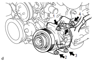
2. INSTALL COOLER COMPRESSOR ASSEMBLY (for 2TR-FE)
(a) Using an E8 ''TORX'' socket wrench, temporarily install the cooler compressor assembly with the 2 stud bolts.
Torque:
10 N·m {102 kgf·cm, 7 ft·lbf}
|
(b) Install the 2 nuts and 2 bolts in the order shown in the illustration. Torque: 21 N·m {214 kgf·cm, 16 ft·lbf} |
|
(c) Connect the connector.
3. INSTALL COOLER COMPRESSOR ASSEMBLY (for 2GR-FKS)
(a) Using an E8 ''TORX'' socket wrench, temporarily install the cooler compressor assembly with the 2 stud bolts.
|
(b) Install the 2 nuts and 2 bolts in the order shown in the illustration. Torque: 21 N·m {214 kgf·cm, 16 ft·lbf} |
|

(c) Connect the connector.
4. INSTALL DISCHARGE HOSE SUB-ASSEMBLY
(a) Remove the vinyl tape from discharge hose sub-assembly and connecting portion of the cooler compressor assembly.
(b) Apply sufficient compressor oil to a new O-ring and fitting surface of the cooler compressor assembly.
Compressor oil:
PSD1 or equivalent
(c) Install the O-ring to the discharge hose sub-assembly.
(d) Install the discharge hose sub-assembly to the cooler compressor assembly with the bolt.
Torque:
9.8 N·m {100 kgf·cm, 87 in·lbf}
5. INSTALL SUCTION HOSE SUB-ASSEMBLY (for 2TR-FE)
(a) Remove the vinyl tape from the suction hose sub-assembly.
(b) Apply sufficient compressor oil to a new O-ring and fitting surface of the cooler compressor assembly.
Compressor oil:
PSD1 or equivalent
(c) Install the O-ring to the suction hose sub-assembly.
(d) Install the suction hose sub-assembly to the cooler compressor assembly with the bolt.
Torque:
9.8 N·m {100 kgf·cm, 87 in·lbf}
(e) Install the suction hose sub-assembly with the bolt.
Torque:
7.5 N·m {76 kgf·cm, 66 in·lbf}
6. INSTALL SUCTION HOSE SUB-ASSEMBLY (for 2GR-FKS)
(a) Remove the vinyl tape from the suction hose sub-assembly.
(b) Apply sufficient compressor oil to a new O-ring and fitting surface of the cooler compressor assembly.
Compressor oil:
PSD1 or equivalent
(c) Install the O-ring to the suction hose sub-assembly.
(d) Install the suction hose sub-assembly to the cooler compressor assembly with the bolt.
Torque:
9.8 N·m {100 kgf·cm, 87 in·lbf}
(e) Install the suction hose sub-assembly with the bolt.
Torque:
7.5 N·m {76 kgf·cm, 66 in·lbf}
7. INSTALL FRONT UPPER FENDER APRON SEAL
(a) Install the front upper fender apron seal with the 5 clips.
8. INSTALL GENERATOR ASSEMBLY (for 2GR-FKS)
Click here .gif)
9. INSPECT FAN AND GENERATOR V BELT (for 2TR-FE)
Click here
10. CONNECT CABLE TO NEGATIVE BATTERY TERMINAL
Torque:
5.4 N·m {55 kgf·cm, 48 in·lbf}
NOTICE:
When disconnecting the cable, some systems need to be initialized after the cable is reconnected.
Click here
11. CHARGE AIR CONDITIONING SYSTEM WITH REFRIGERANT
Click here
12. WARM UP ENGINE
Click here
13. INSPECT FOR REFRIGERANT LEAK
Click here
 Reassembly
REASSEMBLY
PROCEDURE
1. INSTALL COMPRESSOR PICK UP SENSOR
(a) Install the compressor pick up sensor with the 3 screws.
(b) Engage the clam ...
 Condenser
...
Other materials:
Head restraints
Head restraints are provided for all seats.
■ Adjusting the head restraints
Bench type front seat
Up
Pull the head restraints up.
Down
Push the head restraint down while pushing the lock release button.
Separated type front seat
Up
Pull the head restraints up.
Down
Push th ...
Turn Signal Switch Circuit
DESCRIPTION
The combination meter assembly receives the turn signal switch information and
controls the turn signal lights.
WIRING DIAGRAM
PROCEDURE
1.
READ VALUE USING TECHSTREAM (TURN SIGNAL SWITCH)
(a) Connect the Techstream to the DLC3.
(b) Turn the igni ...
Emission inspection and maintenance (I/M) programs
Some states have vehicle emission inspection programs which include OBD (On
Board Diagnostics) checks. The OBD system monitors the operation of the emission
control system.
■ If the malfunction indicator lamp comes on
The OBD system determines that a problem exists somewhere in the emiss ...
