Toyota Tacoma (2015-2018) Service Manual: Tachometer Malfunction
DESCRIPTION
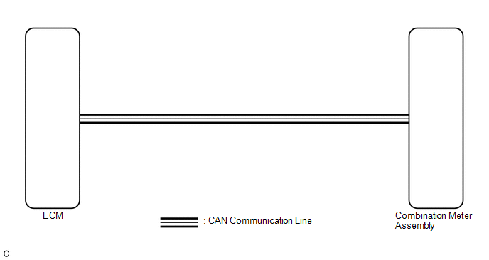
In this circuit, the meter CPU receives engine speed signals from the ECM using the CAN communication system (CAN V1 Bus). The meter CPU displays the engine speed calculated based on the data received from the ECM.
WIRING DIAGRAM
PROCEDURE
|
1. |
CHECK CAN COMMUNICATION SYSTEM |
(a) Check if a CAN communication DTC is output (See page
.gif) ).
).
|
Result |
Proceed to |
|---|---|
|
CAN communication DTC is not output |
A |
|
CAN communication DTC is output |
B |
| B | .gif) |
GO TO CAN COMMUNICATION SYSTEM |
|
.gif)
|
2. |
PERFORM ACTIVE TEST USING TECHSTREAM (TACHOMETER OPERATION) |
(a) Connect the Techstream to the DLC3.
(b) Turn the ignition switch to ON.
(c) Turn the Techstream on.
(d) Enter the following menus: Body Electrical / Combination Meter / Active Test.
(e) According to the display on the Techstream, perform the Active Test.
Combination Meter|
Tester Display |
Test Part |
Control Range |
Diagnostic Note |
|---|---|---|---|
|
TachoMeter Operation |
Tachometer |
OFF, 0, 1000, 2000, 3000, 4000, 5000, 6000, 7000 |
Operate with IG ON and the vehicle is stopped. |
OK:
Tachometer indication is normal.
| NG | |
REPLACE COMBINATION METER ASSEMBLY |
|
|
3. |
READ VALUE USING TECHSTREAM (ENGINE RPM) |
(a) Connect the Techstream to the DLC3.
(b) Start the engine.
(c) Turn the Techstream on.
(d) Enter the following menus: Body Electrical / Combination Meter / Data List.
(e) According to the display on the Techstream, read the Data List.
Combination Meter|
Tester Display |
Measurement Item/Range |
Normal Condition |
Diagnostic Note |
|---|---|---|---|
|
Engine Rpm |
Engine speed/ Min.: 0 rpm, Max.: 12750 rpm |
|
- |
OK:
Engine speed displayed on the Techstream is almost the same as the tachometer indication.
HINT:
Check the engine speed when the engine is fully warmed up, and the air conditioning and all electrical accessories are off.
| NG | |
REPLACE COMBINATION METER ASSEMBLY |
|
|
4. |
CHECK ENGINE CONTROL SYSTEM |
(a) Check if a engine control DTC is output.
- for 2TR-FE: (See page )
- for 2GR-FKS: (See page )
|
Result |
Proceed to |
|---|---|
|
Engine control DTC is not output |
A |
|
Engine control (for 2TR-FE) DTC is output |
B |
|
Engine control (for 2GR-FKS) DTC is output |
C |
| A | |
REPLACE COMBINATION METER ASSEMBLY |
| B | |
GO TO SFI SYSTEM (for 2TR-FE) |
| C | |
GO TO SFI SYSTEM (for 2GR-FKS) |
 Speedometer Malfunction
DESCRIPTION
The meter CPU receives vehicle speed signals from the skid control ECU via the
CAN communication system (CAN V1 Bus). The speed sensor detects the wheel speed
and sends the appropriat ...
 Engine Coolant Temperature Receiver Gauge Malfunction
DESCRIPTION
In this circuit, the meter CPU receives engine coolant temperature signals from
the ECM using the CAN communication system (CAN V1 Bus). The meter CPU displays
engine coolant temperat ...
Other materials:
Front Radar Sensor Incorrect Axial Gap (C1A11)
DESCRIPTION
When the vehicle is determined to be driving in a straight line or on a gradual
curve based on signals from the yaw rate sensor, etc., the millimeter wave radar
sensor assembly performs self diagnosis to check if the sensor beam axis has deviated.
If the millimeter wave radar sens ...
How To Proceed With Troubleshooting
CAUTION / NOTICE / HINT
HINT:
*: Use the Techstream.
PROCEDURE
1.
VEHICLE BROUGHT TO WORKSHOP
NEXT
2.
CUSTOMER PROBLEM ANALYSIS
Click here
(a) Confirm problem s ...
Turn signal lever
Right turn
Left turn
Move and hold the lever partway to
signal a lane change.
The right hand signal will flash until you release the lever.
Move and hold the lever partway
to signal a lane change.
The left hand signal will flash until you release the lever.
■Turn signals can be ...
