Toyota Tacoma (2015-2018) Service Manual: Terminals Of Ecu
TERMINALS OF ECU
CHECK ECM
HINT:
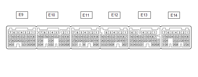
The standard voltage, resistance and waveform between each pair of the ECM terminals is shown in the table below. The appropriate conditions for checking each pair of the terminals is also indicated. The result of checks should be compared with the standard voltage, resistance and waveform for each pair of the terminals as displayed in the Specified Condition column. The illustration above can be used as a reference to identify the ECM terminal locations.
|
Terminal No. (Symbols) |
Wiring Color |
Terminal Description |
Condition |
Specified Condition |
|---|---|---|---|---|
|
E10-23 (VC) - E11-1 (E1)*2 |
LG - W-B |
Neutral position switch power supply |
Ignition switch ON |
4.5 to 5.5 V |
|
E11-1 (E1) - Body ground |
W-B - Body ground |
Ground |
Always |
Below 1 V |
|
E11-22 (NPSW) - E9-23 (ETHW)*2 |
L - BR |
Neutral position switch signal |
Ignition switch ON, shift lever in neutral |
2.7 to 4.3 V |
|
Ignition switch ON, shift lever in any other than neutral |
0.7 to 1.9 V |
|||
|
E12-6 (+BM) - E11-1 (E1) |
GR - W-B |
Power source of throttle actuator |
Always |
11 to 14 V |
|
E12-27 (D) - E11-1 (E1)*1 |
R - W-B |
D shift position signal |
Ignition switch ON, shift lever in D |
11 to 14 V |
|
Ignition switch ON, shift lever not in D |
Below 1 V |
|||
|
E12-27 (D) - E11-1 (E1)*2 |
R - W-B |
Clutch switch input signal |
Ignition switch ON, clutch pedal depressed |
Below 1 V |
|
Ignition switch ON, clutch pedal released |
11 to 14 V |
|||
|
E13-7 (SFTD) - E11-1 (E1)*1 |
R - W-B |
Down-shift position switch signal |
Ignition switch ON and shift lever in S |
11 to 14 V |
|
Ignition switch ON and shift lever in "-" (Down-shift) |
Below 1 V |
|||
|
E13-8 (SFTU) - E11-1 (E1)*1 |
G - W-B |
Up-shift position switch signal |
Ignition switch ON and shift lever in S |
11 to 14 V |
|
Ignition switch ON and shift lever in "+" (Up-shift) |
Below 1 V |
|||
|
E13-15 (ST1-) - E11-1 (E1) |
V - W-B |
Stop light switch assembly signal |
Ignition switch ON, brake pedal depressed |
Below 1 V |
|
Ignition switch ON, brake pedal released |
11 to 14 V |
|||
|
E13-16 (STP) - E11-1 (E1) |
P - W-B |
Stop light switch input signal |
Brake pedal depressed |
11 to 14 V |
|
Brake pedal released |
Below 1 V |
|||
|
E13-17 (CCS) - E11-1 (E1) |
B - W-B |
Cruise control main switch output signal |
CANCEL switch ON |
1509 to 1571 Ω |
|
-SET switch ON |
617 to 643 Ω |
|||
|
+RES switch ON |
235 to 245 Ω |
|||
|
Cruise control main switch (ON-OFF button) not pushed |
1 MΩ or higher |
|||
|
Cruise control main switch (ON-OFF button) pushed |
Below 2.5 Ω |
|||
|
E13-32 (S) - E11-1 (E1)*1 |
P - W-B |
S shift position switch signal |
Ignition switch ON and shift lever in S, "+" or "-" |
11 to 14 V |
|
Ignition switch ON and shift lever not in S, "+" or "-" |
Below 1 V |
|||
|
E14-2 (BATT) - E11-1 (E1) |
L - W-B |
Battery (for measuring battery voltage and for ECM memory) |
Always |
11 to 14 V |
|
E14-20 (TC) - E11-1 (E1) |
G - W-B |
DTC output signal |
Ignition switch ON |
11 to 14 V |
|
Ignition switch ON, connect terminals TC and CG of DLC3 |
Below 2 V |
- *1: for Automatic Transmission
- *2: for Manual Transmission

NOTICE:
Do not apply excessive force to the connector. If a force of 10 kg or more is applied, the connector may be broken.
CHECK FORWARD RECOGNITION CAMERA
|
Terminal No. (Symbol) |
Wiring Color |
Terminal Description |
Condition |
Specified Condition |
|---|---|---|---|---|
|
F46-8 (BZ) - F46-10 (GND) |
L - W-B |
Skid control buzzer output |
Ignition switch to ON, buzzer not sounding |
11 to 14 V |
|
Ignition switch to ON, buzzer sounding |
Below 1 V |
|||
|
F46-7 (IGB) - F46-10 (GND) |
BE - W-B |
Power source |
Ignition switch to ON |
11 to 14 V |
|
Ignition switch off |
Below 1 V |
|||
|
F46-5 (CA1P) - F46-10 (GND) |
L - W-B |
CAN communication signal |
Ignition switch to ON |
Pulse generation (See waveform 1) |
|
F46-11 (CA1N) - F46-10 (GND) |
W - W-B |
CAN communication signal |
Ignition switch to ON |
Pulse generation (See waveform 2) |
|
F46-6 (CANH) - F46-10 (GND) |
B - W-B |
CAN communication signal |
Ignition switch to ON |
Pulse generation (See waveform 1) |
|
F46-12 (CANL) - F46-10 (GND) |
W - W-B |
CAN communication signal |
Ignition switch to ON |
Pulse generation (See waveform 2) |
|
F46-3 (LKSW) - F46-10 (GND) |
GR - W-B |
Steering pad switch assembly signal (distance control signal) |
Ignition switch to ON, steering pad switch assembly (distance control switch) off |
4.75 to 5.25 V |
|
Ignition switch to ON, steering pad switch assembly (distance control switch) on |
Below 1 V |
|||
|
F46-10 (GND) - Body ground |
W-B - Body ground |
Ground |
Always |
Below 1 Ω |
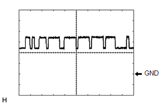
(a) Waveform 1
(1) CAN communication signal
|
Item |
Content |
|---|---|
|
Tester Connection |
|
|
Tool Setting |
1 V/DIV., 10 ÎĽsec./DIV. |
|
Condition |
Ignition switch to ON |
HINT:
The waveform varies depending on the CAN communication signal.
(b) Waveform 2
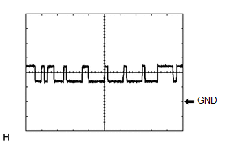
(1) CAN communication signal
|
Item |
Content |
|---|---|
|
Tester Connection |
|
|
Tool Setting |
1 V/DIV., 10 ÎĽsec./DIV. |
|
Condition |
Ignition switch to ON |
HINT:
The waveform varies depending on the CAN communication signal.

|
Terminal No. (Symbol) |
Wiring Color |
Terminal Description |
Condition |
Specified Condition |
|---|---|---|---|---|
|
M8-1 (SGND) - Body ground |
W-B - Body ground |
Ground |
Always |
Below 1 Ω |
|
M8-2 (CA2L) - M8-1 (SGND) |
W - W-B |
CAN communication signal |
Ignition switch to ON |
Pulse generation (See waveform 2) |
|
M8-3 (CA2H) - M8-1 (SGND) |
W-B - W-B |
CAN communication signal |
Ignition switch to ON |
Pulse generation (See waveform 1) |
|
M8-5 (CA1P) - M8-1 (SGND) |
B - W-B |
CAN communication signal |
Ignition switch to ON |
Pulse generation (See waveform 1) |
|
M8-6 (CA1N) - M8-1 (SGND) |
W - W-B |
CAN communication signal |
Ignition switch to ON |
Pulse generation (See waveform 2) |
|
M8-8 (IGB) - M8-1 (SGND) |
LG - W-B |
Power source |
Ignition switch to ON |
11 to 14 V |
CHECK MILLIMETER WAVE RADAR SENSOR
(a) Waveform 1
(1) CAN communication signal
|
Item |
Content |
|---|---|
|
Tester Connection |
|
|
Tool Setting |
1 V/DIV., 10 ÎĽsec./DIV. |
|
Condition |
Ignition switch to ON |
HINT:
The waveform varies depending on the CAN communication signal.
(b) Waveform 2
(1) CAN communication signal
|
Item |
Content |
|---|---|
|
Tester Connection |
|
|
Tool Setting |
1 V/DIV., 10 ÎĽsec./DIV. |
|
Condition |
Ignition switch to ON |
HINT:
The waveform varies depending on the CAN communication signal.
 Problem Symptoms Table
PROBLEM SYMPTOMS TABLE
NOTICE:
Before replacing the ECM, refer to Registration.
w/o Smart Key System: Click here
w/ Smart Key System: Click here
When the millimeter wave rad ...
 Dtc Check / Clear
DTC CHECK / CLEAR
NOTICE:
When the diagnosis system is changed from normal mode to check mode or vice versa,
all DTCs and freeze frame data recorded in normal mode are cleared. Before changing
m ...
Other materials:
Steering Angle Sensor Output Malfunction (C1434)
DESCRIPTION
Steering angle sensor signals are input to the skid control ECU (brake actuator
assembly) via the CAN communication system.
HINT:
When a malfunction occurs in the communication line to the steering angle sensor,
U0126 is output. If a DTC related to the CAN communication line is ou ...
Vehicle Speed Sensor Circuit (C1AA3)
DESCRIPTION
The forward recognition camera receives vehicle speed signals from the skid control
ECU. If the skid control ECU receives a vehicle speed sensor malfunction signal,
it informs the forward recognition camera via CAN communication, and DTC C1AA3 is
stored.
DTC No.
...
Before Starting Adjustment
BEFORE STARTING ADJUSTMENT
CAUTION / NOTICE / HINT
NOTICE:
When replacing the windshield glass of a vehicle equipped with a forward recognition
camera, make sure to use a Toyota genuine part. If a non-Toyota genuine part is
used, the forward recognition camera may not be able to be installed ...
