Toyota Tacoma (2015-2018) Service Manual: Speaker Output Short (B15C3)
DESCRIPTION
This DTC is stored when a malfunction occurs in the speakers.
|
DTC No. |
DTC Detection Condition |
Trouble Area |
|---|---|---|
|
B15C3 |
A short is detected in the speaker output circuit. |
|
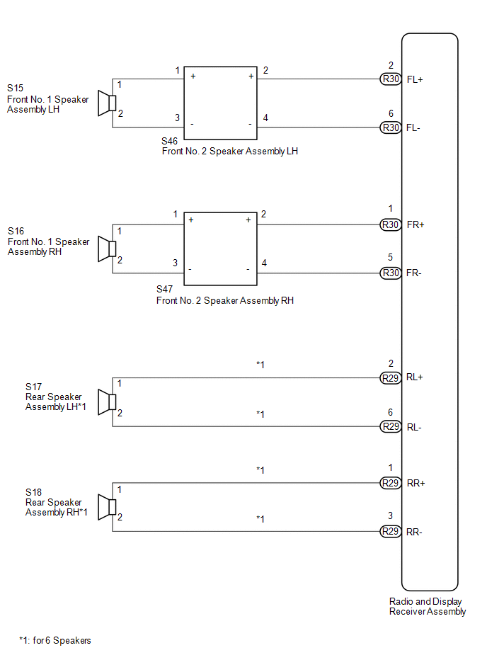
WIRING DIAGRAM
PROCEDURE
|
1. |
CONFIRM MODEL |
(a) Choose the model to be inspected.
Result|
Result |
Proceed to |
|---|---|
|
for 6 Speakers |
A |
|
for 4 Speakers |
B |
| B | .gif) |
GO TO STEP 8 |
|
.gif)
|
2. |
CHECK HARNESS AND CONNECTOR (RADIO AND DISPLAY RECEIVER ASSEMBLY - BODY GROUND) |
(a) Disconnect the R30 and R29 radio and display receiver assembly connectors.
(b) Disconnect the S46 and S47 front No. 2 speaker assembly connectors.
(c) Disconnect the S17 and S18 rear speaker assembly connectors.
(d) Measure the resistance between the radio and display receiver assembly and body ground to check for a short circuit in the wire harness.
Standard Resistance:
|
Tester Connection |
Condition |
Specified Condition |
|---|---|---|
|
R30-1 (FR+) - Body ground |
Always |
10 kΩ or higher |
|
R30-5 (FR-) - Body ground |
Always |
10 kΩ or higher |
|
R30-2 (FL+) - Body ground |
Always |
10 kΩ or higher |
|
R30-6 (FL-) - Body ground |
Always |
10 kΩ or higher |
|
R29-1 (RR+) - Body ground |
Always |
10 kΩ or higher |
|
R29-3 (RR-) - Body ground |
Always |
10 kΩ or higher |
|
R29-2 (RL+) - Body ground |
Always |
10 kΩ or higher |
|
R29-6 (RL-) - Body ground |
Always |
10 kΩ or higher |
| NG | |
REPAIR OR REPLACE HARNESS OR CONNECTOR |
|
|
3. |
CHECK HARNESS AND CONNECTOR (FRONT NO. 2 SPEAKER ASSEMBLY - BODY GROUND) |
(a) Disconnect the S15 and S16 front No. 1 speaker assembly connectors.
(b) Disconnect the S46 and S47 front No. 2 speaker assembly connectors.
(c) Measure the resistance between each of the front No. 2 speaker assemblies and body ground to check for a short circuit in the wire harness.
Standard Resistance:
|
Tester Connection |
Condition |
Specified Condition |
|---|---|---|
|
S47-1 (+) - Body ground |
Always |
10 kΩ or higher |
|
S47-3 (-) - Body ground |
Always |
10 kΩ or higher |
|
S46-1 (+) - Body ground |
Always |
10 kΩ or higher |
|
S46-3 (-) - Body ground |
Always |
10 kΩ or higher |
| NG | |
REPAIR OR REPLACE HARNESS OR CONNECTOR |
|
|
4. |
INSPECT FRONT NO. 1 SPEAKER ASSEMBLY |
(a) Remove the front No. 1 speaker assembly (See page
.gif) ).
).
|
(b) Measure the resistance according to the value(s) in the table below. Standard Resistance:
|
|
| NG | |
REPLACE FRONT NO. 1 SPEAKER ASSEMBLY |
|
|
5. |
INSPECT FRONT NO. 2 SPEAKER ASSEMBLY |
(a) Remove the front No. 2 speaker assembly (See page
).
|
(b) Measure the resistance according to the value(s) in the table below. Standard Resistance:
|
|
| NG | |
REPLACE FRONT NO. 2 SPEAKER ASSEMBLY |
|
|
6. |
REPLACE FRONT NO. 2 SPEAKER ASSEMBLY |
(a) Replace the front No. 2 speaker assembly with a new or known good one (See
page ).
(b) Clear the DTCs (See page ).
(c) Recheck for DTCs and check that no DTCs are output.
OK:
No DTCs are output.
HINT:
- Connect all the connectors to the front No. 2 speaker assemblies that were disconnected.
- When there is a possibility that either the right or left front No. 2 speaker assembly is defective, inspect by interchanging the right one with the left one.
- Perform the above inspection on both the LH and RH side.
| OK | |
END |
|
|
7. |
INSPECT REAR SPEAKER ASSEMBLY |
(a) Remove the rear speaker assembly (See page
).
|
(b) Measure the resistance according to the value(s) in the table below. Standard Resistance:
|
|
| OK | |
REPLACE RADIO AND DISPLAY RECEIVER ASSEMBLY |
| NG | |
REPLACE REAR SPEAKER ASSEMBLY |
|
8. |
CHECK HARNESS AND CONNECTOR (RADIO AND DISPLAY RECEIVER ASSEMBLY - BODY GROUND) |
(a) Disconnect the R30 radio and display receiver assembly connector.
(b) Disconnect the S46 and S47 front No. 2 speaker assembly connectors.
(c) Measure the resistance between the radio and display receiver assembly and body ground to check for a short circuit in the wire harness.
Standard Resistance:
|
Tester Connection |
Condition |
Specified Condition |
|---|---|---|
|
R30-1 (FR+) - Body ground |
Always |
10 kΩ or higher |
|
R30-5 (FR-) - Body ground |
Always |
10 kΩ or higher |
|
R30-2 (FL+) - Body ground |
Always |
10 kΩ or higher |
|
R30-6 (FL-) - Body ground |
Always |
10 kΩ or higher |
| NG | |
REPAIR OR REPLACE HARNESS OR CONNECTOR |
|
|
9. |
CHECK HARNESS AND CONNECTOR (FRONT NO. 2 SPEAKER ASSEMBLY - BODY GROUND) |
(a) Disconnect the S15 and S16 front No. 1 speaker assembly connectors.
(b) Disconnect the S46 and S47 front No. 2 speaker assembly connectors.
(c) Measure the resistance between each of the front No. 2 speaker assemblies and body ground to check for a short circuit in the wire harness.
Standard Resistance:
|
Tester Connection |
Condition |
Specified Condition |
|---|---|---|
|
S46-1 (+) - Body ground |
Always |
10 kΩ or higher |
|
S46-3 (-) - Body ground |
Always |
10 kΩ or higher |
|
S47-1 (+) - Body ground |
Always |
10 kΩ or higher |
|
S47-3 (-) - Body ground |
Always |
10 kΩ or higher |
| NG | |
REPAIR OR REPLACE HARNESS OR CONNECTOR |
|
|
10. |
INSPECT FRONT NO. 1 SPEAKER ASSEMBLY |
(a) Remove the front No. 1 speaker assembly (See page
).
|
(b) Measure the resistance according to the value(s) in the table below. Standard Resistance:
|
|
| NG | |
REPLACE FRONT NO. 1 SPEAKER ASSEMBLY |
|
|
11. |
INSPECT FRONT NO. 2 SPEAKER ASSEMBLY |
(a) Remove the front No. 2 speaker assembly (See page
).
|
(b) Measure the resistance according to the value(s) in the table below. Standard Resistance:
|
|
| NG | |
REPLACE FRONT NO. 2 SPEAKER ASSEMBLY |
|
|
12. |
REPLACE FRONT NO. 2 SPEAKER ASSEMBLY |
(a) Replace the front No. 2 speaker assembly with a new or known good one (See
page ).
(b) Clear the DTCs (See page ).
(c) Recheck for DTCs and check that no DTCs are output.
OK:
No DTCs are output.
HINT:
- Connect all the connectors to the front No. 2 speaker assemblies that were disconnected.
- When there is a possibility that either the right or left front No. 2 speaker assembly is defective, inspect by interchanging the right one with the left one.
- Perform the above inspection on both the LH and RH side.
| OK | |
END |
| NG | |
REPLACE RADIO AND DISPLAY RECEIVER ASSEMBLY |
 Short in GPS Antenna (B15C0,B15C1)
DESCRIPTION
These DTCs are stored when a malfunction occurs in the navigation antenna assembly.
DTC No.
DTC Detection Condition
Trouble Area
B15C0
...
 A/C ECU Vehicle Information Reading/Writing Processor Malfunction (B15F5)
DESCRIPTION
This DTC is stored when items controlled by the air conditioning amplifier assembly
cannot be customized via the audio and visual system vehicle customization screen.
HINT:
The air co ...
Other materials:
Lost Communication with Yaw Rate Sensor Module (U0123,U0126,U0129,U0142,U0155)
DESCRIPTION
These DTCs are output when a communication malfunction occurs between the sensors
and ECUs.
DTC No.
Detection Item
DTC Detection Condition
Trouble Area
U0123
Lost Communication with Yaw Rate Sensor Module
...
Using the interior lights
Interior lights list
Interior light
Personal lights (Access Cab and
Double Cab models)
■Illuminated entry system
When the interior light switch is in the DOOR position, the interior light automatically
turns on/off according to whether the doors are locked/unlocked and whether the ...
Installation
INSTALLATION
PROCEDURE
1. INSTALL POWER STEERING LINK
(a) Insert the power steering link into the vehicle in the order shown in the
illustration.
Install in this Direction (1)
Install in this Direction (2)
(b) Temporarily install the po ...
