Toyota Tacoma (2015-2018) Service Manual: Disassembly
DISASSEMBLY
PROCEDURE
1. REMOVE FRONT BRAKE SHOE
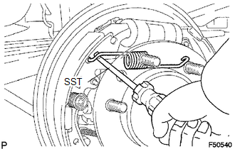
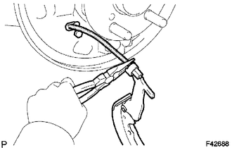
(a) Using SST, remove the shoe return spring from the front brake shoe.
SST: 09921-00010
|
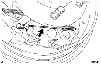
(b) Using needle-nose pliers, remove the return spring. |
|
|
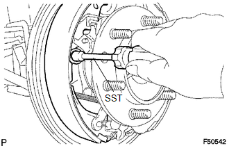
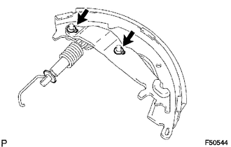
(c) Using SST, remove the shoe hold down spring cup, shoe hold down spring and pin. SST: 09718-00010 |
|
(d) Remove the parking brake shoe strut lower.
(e) Remove the tension spring and front brake shoe.
(f) Remove the automatic adjust lever spring and automatic adjust lever LH from the front brake shoe.
2. REMOVE REAR BRAKE SHOE
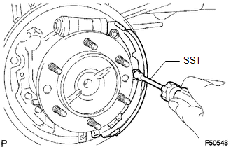
(a) Using SST, remove the shoe hold down spring cup, shoe hold down spring and pin.
SST: 09718-00010
|
(b) Using needle-nose pliers, disconnect the parking brake cable No. 3 and remove the rear brake shoe. |
|
|
(c) Using a screwdriver, remove the 2 C-washers, parking brake shoe lever, parking brake reaction lever and parking brake shoe strut set. |
|
3. REMOVE FRONT OR UPPER REAR WHEEL BRAKE CYLINDER ASSEMBLY
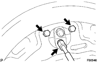
(a) Using a union nut wrench, disconnect the brake tube, and use a container to collect the brake fluid as it flows out.
(b) Remove the 2 bolts and rear wheel brake cylinder assembly.
4. REMOVE REAR WHEEL CYLINDER CUP KIT
(a) Remove the 2 wheel cylinder boots from the rear wheel brake cylinder.
(b) Remove the 2 pistons and compression spring.
(c) Remove the 2 cylinder cups from each piston.
(d) Remove the bleeder plug cap and bleeder plug from the rear wheel brake cylinder.
 Components
COMPONENTS
ILLUSTRATION
...
 Removal
REMOVAL
PROCEDURE
1. REMOVE REAR WHEEL
2. DRAIN BRAKE FLUID
HINT:
Immediately wash off any brake fluid that comes into contact with any painted
surfaces.
3. REMOVE REAR BRAKE DRUM SUB-ASSEMBLY ...
Other materials:
Removal
REMOVAL
CAUTION / NOTICE / HINT
HINT:
If the bumper is damaged, there is a possibility that the installation area of
the blind spot monitor sensor may be deformed and the blind spot monitor system
may not operate correctly, so visually inspect the blind spot monitor sensor installation
area ...
Components
COMPONENTS
ILLUSTRATION
*1
RADIATOR GRILLE
-
-
ILLUSTRATION
*A
for Type A
*B
for Type B
*C
for Type C
-
-
*1
MILLIMET ...
Occupant Classification ECU Malfunction (B1795)
DESCRIPTION
DTC B1795 is set when a malfunction is detected in the occupant detection ECU.
Troubleshoot DTC B1771 first when both DTCs B1771 and B1795 are present.
DTC No.
DTC Detections Conditions
Trouble Areas
B1795
Occupant detection ...
