Toyota Tacoma (2015-2018) Service Manual: System Diagram
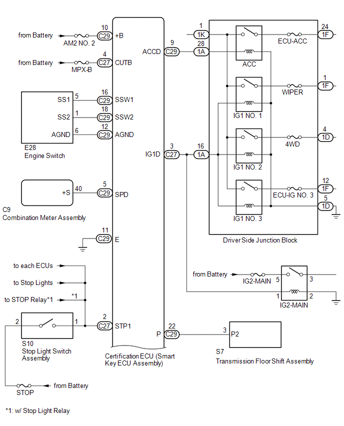
SYSTEM DIAGRAM
|
Component |
Outline |
|---|---|
|
Engine switch
|
|
|
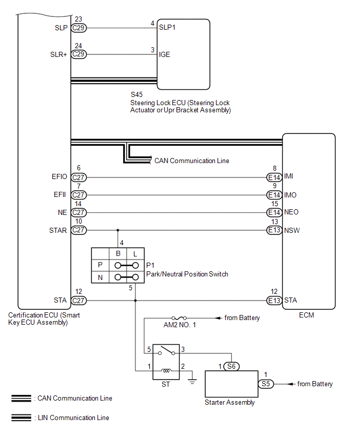
Certification ECU (smart key ECU assembly) |
|
|
ECM |
|
|
Steering lock ECU (steering lock actuator or UPR bracket assembly) |
|
|
Combination meter assembly |
|
|
IG, ACC relay |
Turns on/off according to the certification ECU (smart key ECU) and provides power to each system. |
|
Stop light switch assembly |
Detects that the brake pedal has been depressed (switch is on) and outputs a signal to the certification ECU (smart key ECU assembly). |
|
No. 1 indoor electrical key antenna assembly (front floor) No. 2 indoor electrical key antenna assembly (rear floor) |
Sends the request code from the certification ECU (smart key ECU assembly) and forms the vehicle interior detection area. |
|
Electrical key and TPMS receiver assembly |
Receives the smart key system code/wireless code sent from the key and sends it to the certification ECU (smart key ECU assembly). |
|
Electrical key transmitter sub-assembly |
Sends the ID code upon receiving a request signal. |
 Parts Location
PARTS LOCATION
ILLUSTRATION
ILLUSTRATION
ILLUSTRATION
ILLUSTRATION
...
 How To Proceed With Troubleshooting
CAUTION / NOTICE / HINT
HINT:
Use these procedures to troubleshoot the smart key system (for Start
Function).
*: Use the Techstream.
PROCEDURE
1.
VEHIC ...
Other materials:
Wireless remote control battery
Replace the battery with a new one if it is discharged.
■ You will need the following items:
Lithium battery CR2032
■ Replacing the battery
Remove the cover using a coin protected with tape etc.
Remove the discharged transmitter battery.
Insert a new battery with the “+” te ...
Transfer Case Front Oil Seal
Components
COMPONENTS
ILLUSTRATION
Replacement
REPLACEMENT
PROCEDURE
1. DRAIN TRANSFER OIL
2. SUPPORT TRANSMISSION ASSEMBLY
3. REMOVE NO. 3 FRAME CROSSMEMBER SUB-ASSEMBLY
4. REMOVE TRANSFER CASE LOWER PROTECTOR
5. REMOVE FRONT PROPELLER SHAFT ASSEMBLY
(See page )
6. ...
Slip Indicator Light Remains ON
DESCRIPTION
The skid control ECU (brake actuator assembly) is connected to the combination
meter assembly via CAN communication.
The slip indicator light blinks during VSC and/or TRAC operation.
If a malfunction is detected, the slip indicator light comes on to warn the driver
(See page ).
...
