Toyota Tacoma (2015-2018) Service Manual: Parts Location
PARTS LOCATION
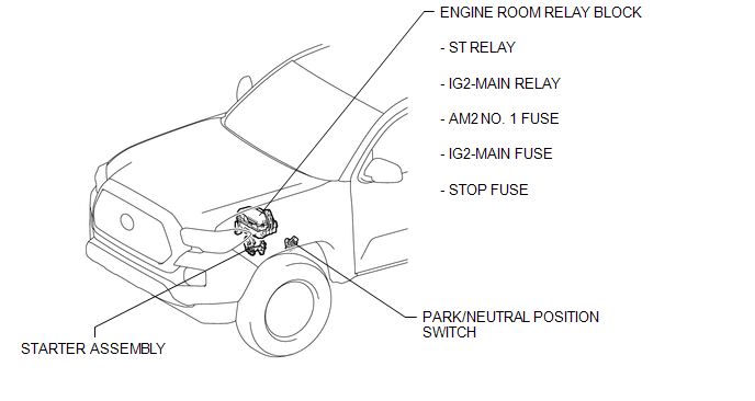
ILLUSTRATION
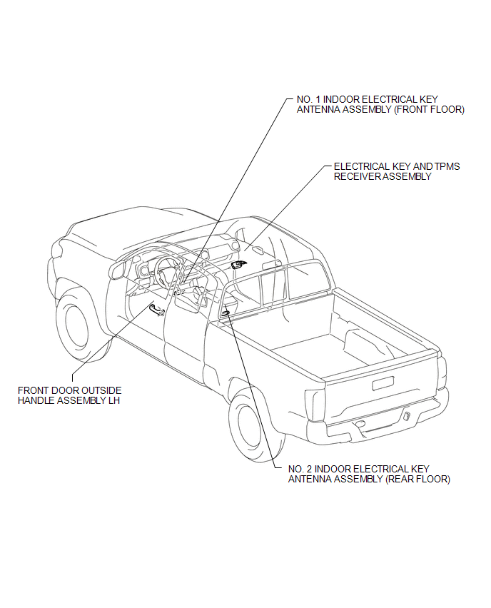
ILLUSTRATION
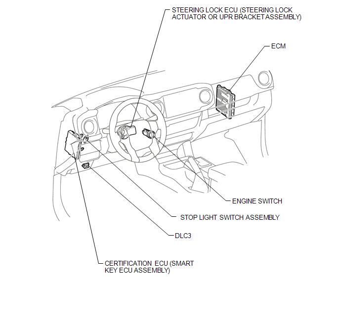
ILLUSTRATION
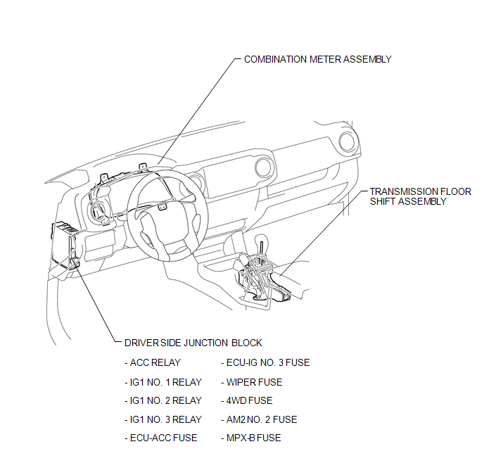
ILLUSTRATION
 Precaution
PRECAUTION
1. CAUTION REGARDING INTERFERENCE WITH ELECTRONIC DEVICES
CAUTION:
People with implantable cardiac pacemakers, cardiac resynchronization
therapy-pacemakers or implantable car ...
 System Diagram
SYSTEM DIAGRAM
Component
Outline
Engine switch
Transponder key amplifier
Turns on the power and starts the eng ...
Other materials:
Transmitter ID1 Error (C2141/41-C2144/44)
DESCRIPTION
The tire pressure warning valve and transmitters that are installed in the tire
and wheel assemblies measure the tire pressure of each wheel. The measured values
are transmitted to the tire pressure warning ECU and receiver in the vehicle as
radio waves. The ECU compares the measu ...
Problem Symptoms Table
PROBLEM SYMPTOMS TABLE
HINT:
Use the table below to help determine the cause of problem symptoms. If multiple
suspected areas are listed, the potential causes of the symptoms are listed in order
of probability in the "Suspected Area" column of the table. Check each symptom by
check ...
Installation
INSTALLATION
CAUTION / NOTICE / HINT
HINT:
Use the same procedure for the RH and LH sides.
The procedure listed below is for the LH side.
PROCEDURE
1. INSTALL FRONT NO. 1 SPEAKER ASSEMBLY
(a) Install the front No. 1 speaker assembly with the 4 screws.
NOTICE:
Do not touch t ...
