Toyota Tacoma (2015-2018) Service Manual: Driver Side Power Window Auto Up / Down Function does not Operate with Power Window Master Switch
DESCRIPTION
If the manual up/down function can be performed but the auto up/down function cannot, then the fail-safe mode may be functioning.
If the power window initialization (See page .gif) ) has not been performed, the auto up/down function will not operate.
) has not been performed, the auto up/down function will not operate.
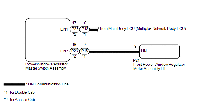
WIRING DIAGRAM
CAUTION / NOTICE / HINT
NOTICE:
- The power window control system uses the LIN communication system. Inspect
the communication function by following How to Proceed with Troubleshooting.
Troubleshoot the power window control system after confirming that the communication
system is functioning properly (See page
).
- If the front power window regulator motor assembly LH has been replaced
with a new one, initialize the power window control system (See page
).
- Check that the "D Window Auto Up" and "D Window Auto Down" power window
control system customize settings are "ON" before proceeding with work (See
page ).
- After the catch protection function operates, the auto operation is not performed the first time auto up is performed. All auto up operations performed after the first operate normally
HINT:
If the pulse sensor built into the front power window regulator motor assembly
LH is malfunctioning, the power window control system enters fail-safe mode. The
remote up and down and auto up and down functions cannot be operated during fail-safe
mode. However, the power window can be closed by holding the power window regulator
master switch assembly at the auto up position, and opened manually by pushing down
the power window regulator master switch assembly (See page
).
Click here
PROCEDURE
|
1. |
READ VALUE USING TECHSTREAM (MASTER SWITCH) |
(a) Connect the Techstream to the DLC3.
(b) Turn the ignition switch to ON.
(c) Turn the Techstream on.
(d) Enter the following menus: Body Electrical / Master switch / Data List.
(e) Read the Data List according to the display on the Techstream.
Master Switch|
Tester Display |
Measurement Item/Range |
Normal Condition |
Diagnostic Note |
|---|---|---|---|
|
D Door P/W Auto SW |
Driver side power window auto up/down switch signal / ON or OFF |
ON: Driver side power window auto switch operated OFF: Driver side power window auto switch not operated |
- |
OK:
On the Techstream screen, ON or OFF is displayed accordingly.
| NG | .gif) |
REPLACE POWER WINDOW REGULATOR MASTER SWITCH ASSEMBLY |
|
.gif)
|
2. |
READ VALUE USING TECHSTREAM (D-DOOR MOTOR) |
(a) Enter the following menus: Body Electrical / D-Door Motor / Data List.
(b) Read the Data List according to the display on the Techstream.
D-Door Motor (Front Power Window Regulator Motor Assembly LH)|
Tester Display |
Measurement Item/Range |
Normal Condition |
Diagnostic Note |
|---|---|---|---|
|
D Door P/W Auto SW |
Driver side power window auto up/down switch signal / ON or OFF |
ON: Driver side power window auto switch operated OFF: Driver side power window auto switch not operated |
- |
OK:
On the Techstream screen, ON or OFF is displayed accordingly.
| NG | |
GO TO STEP 5 |
|
|
3. |
PERFORM INITIALIZATION (for Driver Side) |
(a) Initialize the front power window regulator motor assembly LH (See page
).
|
|
4. |
CHECK POWER WINDOW CONTROL SYSTEM (AUTO UP/DOWN FUNCTION) |
(a) Check that the driver side door power window moves when the auto up/down
function of the power window regulator master switch assembly is operated (See page
).
OK:
Driver side auto up/down function is normal.
| OK | |
END (PROBLEM DUE TO INITIALIZATION FAILURE) |
| NG | |
REPLACE FRONT POWER WINDOW REGULATOR MOTOR ASSEMBLY LH |
|
5. |
REPLACE POWER WINDOW REGULATOR MASTER SWITCH ASSEMBLY |
(a) Replace the power window regulator master switch assembly (See page
).
|
|
6. |
CHECK AND REPLACE POWER WINDOW CONTROL SYSTEM (AUTO UP/DOWN FUNCTION) |
(a) Check that the driver side door power window moves when the auto up/down
function of the power window regulator master switch assembly is operated (See page
).
OK:
Driver side auto up/down function is normal.
| OK | |
END (POWER WINDOW REGULATOR MASTER SWITCH ASSEMBLY WAS DEFECTIVE) |
| NG | |
REPLACE FRONT POWER WINDOW REGULATOR MOTOR ASSEMBLY LH |
 Remote Up / Down Function does not Operate
DESCRIPTION
When the ignition switch is ON, the power window regulator master switch assembly
sends remote up/down signals to each power window regulator motor assembly via the
LIN communication ...
 Front Passenger Side Power Window Auto Up / Down Function does not Operate with
Front Passenger Side Power Window Switch
Front Passenger Side Power Window Auto Up / Down Function does not Operate with
Front Passenger Side Power Window Switch
DESCRIPTION
If the manual up/down function can be performed but the auto up/down function
cannot, the fail-safe mode may be functioning.
If the power window initialization (See page
) has not b ...
Other materials:
Removal
REMOVAL
PROCEDURE
1. REMOVE INSTRUMENT PANEL LOWER FINISH PANEL SUB-ASSEMBLY
(See page )
2. REMOVE DRIVER SIDE JUNCTION BLOCK
(a) Disconnect the 5 connectors on the front side.
(b) Remove the 2 nuts to separate the driver side j ...
Installation
INSTALLATION
CAUTION / NOTICE / HINT
HINT:
The following procedures are for BD22 (w/ Differential Lock).
PROCEDURE
1. INSTALL REAR DIFFERENTIAL CARRIER ASSEMBLY
(a) Clean the contact surfaces of the rear differential carrier assembly and
axle housing.
(b) Install the rear differential carri ...
Removal
REMOVAL
PROCEDURE
1. REMOVE PROPELLER SHAFT WITH CENTER BEARING ASSEMBLY
(a) Place matchmarks on the propeller shaft flange yoke and differential
flange.
Text in Illustration
*a
Matchmark
...
