Toyota Tacoma (2015-2018) Service Manual: Removal
REMOVAL
PROCEDURE
1. REMOVE INSTRUMENT PANEL LOWER FINISH PANEL SUB-ASSEMBLY
(See page .gif) )
)
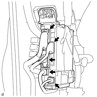
2. REMOVE DRIVER SIDE JUNCTION BLOCK
|
(a) Disconnect the 5 connectors on the front side. |
|
|
(b) Remove the 2 nuts to separate the driver side junction block. |
|
|
(c) Disconnect the 2 connectors on the back side to remove the driver side junction block. |
|
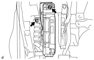
3. REMOVE MAIN BODY ECU (MULTIPLEX NETWORK BODY ECU)
|
(a) Press the claw of the driver side junction block as shown in the illustration to release the lock. Text in Illustration
|
|
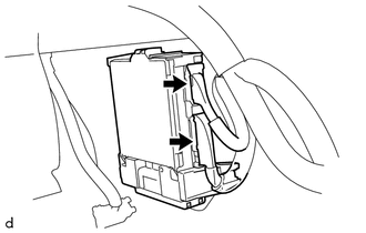
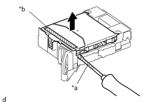
(b) With the driver side junction block lock released, insert a screwdriver with its tip wrapped in protective tape horizontally between the main body ECU (multiplex network body ECU) and driver side junction block.
NOTICE:
- Use a screwdriver with a diameter between 5.0 mm (0.197 in.) and 6.3 mm (0.248 in.) and a length of approximately 90 mm (3.54 in.).
- Do not insert the screwdriver under the connector socket of the main body ECU (multiplex network body ECU).
|
(c) Using a screwdriver with its tip wrapped in protective tape, carefully raise the main body ECU (multiplex network body ECU) to the position where the connector becomes disconnected. Text in Illustration
NOTICE:
|
|
|
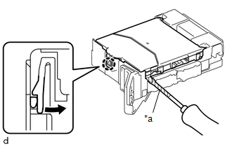
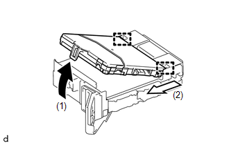
(d) Raise the main body ECU (multiplex network body ECU) and disengage the 2 guides as shown by the arrow (1), and then pull it out as shown by the arrow (2) in the illustration to remove it. NOTICE: Do not touch the main body ECU (multiplex network body ECU) connector. |
|
 Installation
INSTALLATION
PROCEDURE
1. INSTALL MAIN BODY ECU (MULTIPLEX NETWORK BODY ECU)
NOTICE:
Make sure that the connecting surfaces are free of foreign matter.
Do not touch the main body EC ...
 Power Steering
...
Other materials:
Installation
INSTALLATION
CAUTION / NOTICE / HINT
HINT:
Perform "Inspection After Repairs" after replacing the engine assembly, cylinder
head sub-assembly, camshaft, No. 2 camshaft, No. 3 camshaft sub-assembly, No. 4
camshaft sub-assembly, camshaft timing gear assembly, camshaft timing exhaust g ...
Operation Check
OPERATION CHECK
INPUT SIGNAL CHECK
*a
+RES
*b
-SET
*c
ON-OFF
*d
CANCEL
(a) Connect the Techstream to the DLC3.
(b) Check the cruise control main switch using the Data List functio ...
Removal
REMOVAL
CAUTION / NOTICE / HINT
HINT:
Use the same procedure for the RH side and LH side.
The following procedure is for the LH side.
PROCEDURE
1. PRECAUTION
NOTICE:
After turning the ignition switch off, waiting time may be required before disconnecting
the cable from the ...
