Toyota Tacoma (2015-2018) Service Manual: Remote Up / Down Function does not Operate
DESCRIPTION
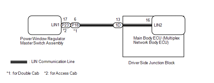
When the ignition switch is ON, the power window regulator master switch assembly sends remote up/down signals to each power window regulator motor assembly via the LIN communication line.
WIRING DIAGRAM
CAUTION / NOTICE / HINT
NOTICE:
- The power window control system uses the LIN communication system. Inspect
the communication function by following How to Proceed with Troubleshooting.
Troubleshoot the power window control system after confirming that the communication
system is functioning properly (See page
.gif) ).
). - If a power window regulator motor assembly has been replaced with a
new one, initialize the power window control system (See page
).
PROCEDURE
|
1. |
READ VALUE USING TECHSTREAM (MAIN BODY) |
(a) Connect the Techstream to the DLC3.
(b) Turn the ignition switch to ON.
(c) Turn the Techstream on.
(d) Enter the following menus: Body Electrical / Main Body / Data List.
(e) Read the Data List according to the display on the Techstream.
Main Body (Main Body ECU)|
Tester Display |
Measurement Item/Range |
Normal Condition |
Diagnostic Note |
|---|---|---|---|
|
Communication P-Door Motor |
Connection status between front power window regulator motor assembly RH and main body ECU / OK or STOP |
OK: Normal communication STOP: Communication stopped |
- |
|
Communication Master SW |
Connection status between multiplex network master switch and main body ECU / OK or STOP |
OK: Normal communication STOP: Communication stopped |
- |
OK:
On the Techstream screen, OK is displayed.
| NG | .gif) |
GO TO LIN COMMUNICATION SYSTEM (Proceed to How to Proceed with Troubleshooting) |
|
.gif)
|
2. |
READ VALUE USING TECHSTREAM (MASTER SWITCH) |
(a) Enter the following menus: Body Electrical / Master Switch / Data List.
(b) Read the Data List according to the display on the Techstream.
Master Switch (Multiplex Network Master Switch Assembly)|
Tester Display |
Measurement Item/Range |
Normal Condition |
Diagnostic Note |
|---|---|---|---|
|
P Door P/W Auto SW |
Front passenger side power window auto up/down switch signal / ON or OFF |
ON: Front passenger side power window auto switch operated OFF: Front passenger side power window auto switch not operated |
- |
|
P Door P/W Up SW |
Front passenger side power window manual up switch signal / ON or OFF |
ON: Front passenger side power window manual up switch operated OFF: Front passenger side power window manual up switch not operated |
- |
|
P Door P/W Down SW |
Front passenger side power window manual down switch signal / ON or OFF |
ON: Front passenger side power window manual down switch operated OFF: Front passenger side power window manual down switch not operated |
- |
|
Window Lock Switch Status |
Window lock switch signal / ON or OFF |
ON: Window lock switch LOCK position OFF: Window lock switch UNLOCK position |
- |
OK:
On the Techstream screen, ON or OFF is displayed accordingly.
Result|
Result |
Proceed to |
|---|---|
|
NG |
A |
|
OK (Front passenger side power window remote up/down function does not operate) |
B |
| A | |
REPLACE POWER WINDOW REGULATOR MASTER SWITCH ASSEMBLY |
| B | |
REPLACE FRONT POWER WINDOW REGULATOR MOTOR ASSEMBLY RH |
 Front Passenger Side Power Window does not Operate with Front Passenger Side
Power Window Switch
Front Passenger Side Power Window does not Operate with Front Passenger Side
Power Window Switch
DESCRIPTION
When the engine is running or the ignition switch is ON, the front power window
regulator motor assembly RH is operated by the front power window regulator switch
assembly RH. The fro ...
 Driver Side Power Window Auto Up / Down Function does not Operate with Power
Window Master Switch
Driver Side Power Window Auto Up / Down Function does not Operate with Power
Window Master Switch
DESCRIPTION
If the manual up/down function can be performed but the auto up/down function
cannot, then the fail-safe mode may be functioning.
If the power window initialization (See page
) has ...
Other materials:
Center Airbag Sensor Communication Stop Mode
DESCRIPTION
Detection Item
Symptom
Trouble Area
Center Airbag Sensor Communication Stop Mode
Either condition is met:
Communication stop for "Airbag" is indicated on the "Communication
Bus Check" sc ...
Front Passenger Side Seat Belt Warning Light Malfunction
DESCRIPTION
The occupant classification ECU detects the state of the front seat inner belt
assembly RH and load sensor when the front passenger side seat is occupied with
the ignition switch ON. If the front passenger side seat belt is not fastened, the
front passenger side seat belt warning ...
Installation
INSTALLATION
PROCEDURE
1. INSTALL GENERATOR ASSEMBLY
(a) Install the generator bracket to the generator assembly with the bolt.
Torque:
20 N·m {204 kgf·cm, 15 ft·lbf}
(b) Install the generator assembly with the 2 bolts.
Torque:
43 N·m {438 kgf·cm, 32 ft·lbf}
(c) Connect the generato ...
