Toyota Tacoma (2015-2018) Service Manual: System Diagram
SYSTEM DIAGRAM
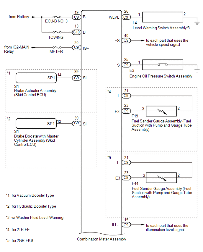
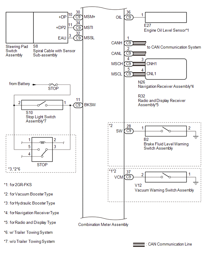
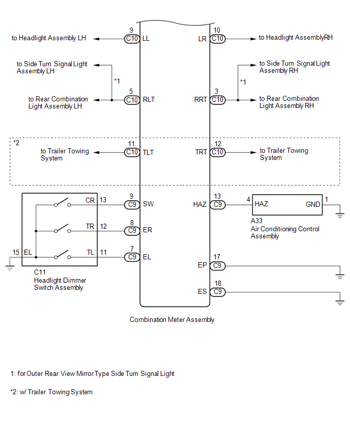
 System Description
SYSTEM DESCRIPTION
Text in Illustration
*a
Indication Example
*b
Tachometer
*c
Engine Coolant Temperature Receiver Gauge
...
 Initialization
INITIALIZATION
1. MAINTENANCE REQUIRED REMINDER RESET PROCEDURE
HINT:
Models with Maintenance Required Reminder Function.
(1) Turn the ignition switch to ON.
(2) Using the steering pad switch ass ...
Other materials:
Speaker Output Short (B15C3)
DESCRIPTION
This DTC is stored when a malfunction occurs in the speakers.
DTC No.
DTC Detection Condition
Trouble Area
B15C3
A short is detected in the speaker output circuit.
Harness or connector
Speaker
...
Indicators and warning lights
The indicator and warning lights on the instrument cluster and center panel
inform the driver of the status of the vehicle’s various systems.
Instrument cluster
Center panel
■ Indicators
The indicators inform the driver of the operating state of the vehicle’s various
systems. ...
No Response from Steering Lock ECU (B2786)
DESCRIPTION
This DTC is stored when LIN communication between the certification ECU (smart
key ECU assembly) and steering lock ECU (steering lock actuator or upper bracket
assembly) stops for 10 seconds or more.
DTC No.
DTC Detection Condition
Trouble Area
...
