Toyota Tacoma (2015-2018) Service Manual: Starting System
Parts Location
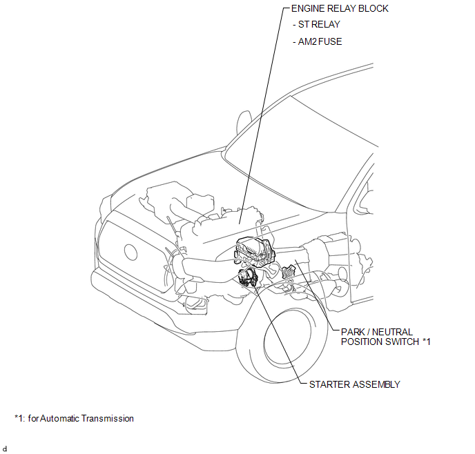
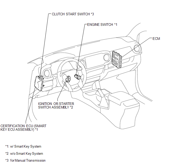
PARTS LOCATION
ILLUSTRATION
ILLUSTRATION
Precaution
PRECAUTION
1. IGNITION SWITCH EXPRESSIONS
(a) The type of ignition switch used on this model differs depending on the specifications of the vehicle. The expressions listed in the table below are used in this section.
|
Expression |
Ignition Switch (Position) |
Engine Switch (Condition) |
|---|---|---|
|
Ignition Switch off |
LOCK |
Off |
|
Ignition Switch ACC |
ACC |
On (ACC) |
|
Ignition Switch ON |
ON |
On (IG) |
|
Engine Start |
START |
Start |
Inspection
INSPECTION
PROCEDURE
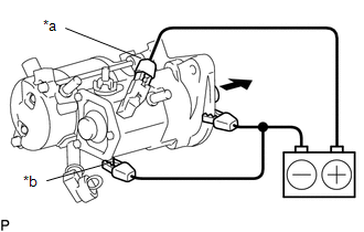
1. INSPECT STARTER ASSEMBLY
CAUTION:
As a large electric current passes through the cable during this inspection, a thick cable must be used. If not, the cable may become hot and cause injury.
NOTICE:
The following tests must each be performed within 3 to 5 seconds to prevent the coil from burning out.
(a) Mount the starter in a vise between aluminum plates.
NOTICE:
Do not overtighten the vise.
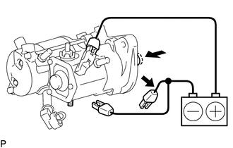
(b) Perform the pull-in test.
(1) Remove the nut and disconnect the lead wire from terminal C.
|
(2) Connect the battery to the magnet starter switch as shown in the illustration. Then check that the clutch pinion gear extends. Text in Illustration
If the clutch pinion gear does not move, replace the magnet starter switch assembly. |
|
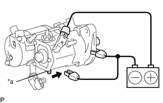
(c) Perform a holding test.
|
(1) Disconnect the negative (-) terminal lead from terminal C with the condition specified in the pull-in test above being maintained. Check that the pinion gear remains out. Text in Illustration
If the clutch pinion gear returns inward, replace the magnet starter switch assembly. |
|
(d) Inspect the clutch pinion gear return.
|
(1) Disconnect the negative (-) terminal lead from the starter body. Check that the clutch pinion gear returns inward. If the clutch pinion gear does not return inward, replace the magnet starter switch assembly. If the clutch pinion gear does not return inward, replace the magnet starter switch assembly |
|
(e) Perform an operation test without load.
(1) Connect the lead wire to the terminal C with the nut.
Torque:
5.9 N·m {60 kgf·cm, 52 in·lbf}
|
(2) Connect the battery and an ammeter to the starter as shown in the illustration. Text in Illustration
|
|
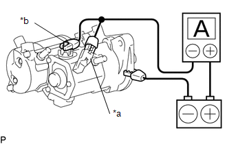
(3) Check that the starter rotates smoothly and steadily while the pinion gear is extended. Then measure the current
Standard current:
90 A or less at 11.5 V
If the result is not as specified, inspect the starter assembly.
HINT:
Inspect the starter brush holder assembly, starter yoke assembly and starter armature assembly. If there is a malfunction, replace the part and perform this test again.
System Diagram
SYSTEM DIAGRAM
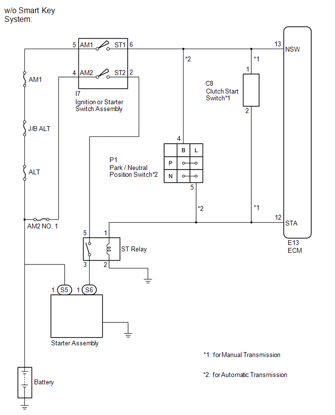
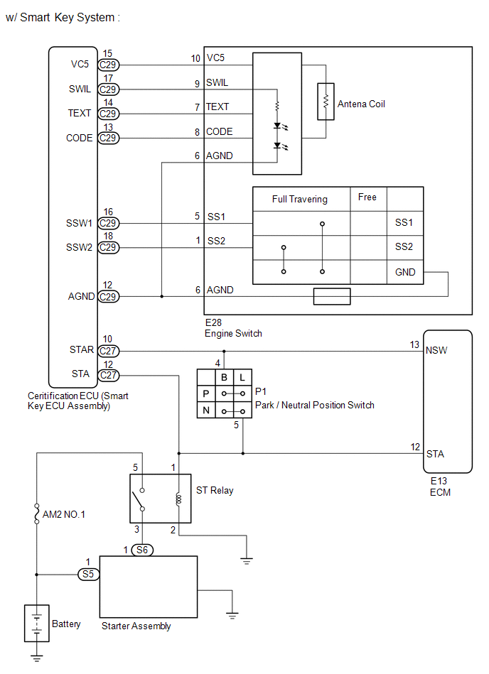
 Starter Relay
Inspection
INSPECTION
PROCEDURE
1. INSPECT STARTER RELAY
(a) Check the resistance.
(1) Measure the resistance according to the value(s) in the table below.
Standard Resistance:
...

Other materials:
Brake Switch "A" Circuit Open (P057113)
DESCRIPTION
DTC No.
DTC Detection Condition
Trouble Area
MIL
Note
P057113
Vehicle Condition:
Cruise control operating
Malfunction Status:
Stop light switch assembly circuit malfunction ...
Reassembly
REASSEMBLY
PROCEDURE
1. INSTALL BRAKE BOOSTER ACCUMULATOR ASSEMBLY
(a) Place the brake booster pump in a vise with a cloth.
(b) Install the brake booster accumulator pipe, compression spring and a new
O-ring.
NOTICE:
Ensure that no foreign matter enters the pump.
(c) Using a socket wrench ...
Driving the vehicle
The following procedures should be observed to ensure safe driving.
■ Starting the engine
■ Driving
Automatic transmission
With the brake pedal depressed,
shift the shift lever to D.
Release the parking brake.
Gradually release the brake pedal
and gently depress the acceler ...
