Toyota Tacoma (2015-2018) Service Manual: Removal
REMOVAL
PROCEDURE
1. REMOVE FRONT DOOR SCUFF PLATE LH (for Double Cab)
Click here .gif)
2. REMOVE FRONT DOOR SCUFF PLATE LH (for Access Cab)
Click here
3. REMOVE COWL SIDE TRIM BOARD LH
Click here
4. REMOVE INSTRUMENT CLUSTER CENTER FINISH PANEL SUB-ASSEMBLY
Click here
5. REMOVE INSTRUMENT CLUSTER FINISH PANEL ASSEMBLY
Click here
6. REMOVE INSTRUMENT PANEL LOWER FINISH PANEL SUB-ASSEMBLY
Click here
7. REMOVE NAVIGATION RECEIVER ASSEMBLY WITH BRACKET (w/ Navigation System)
Click here
8. REMOVE RADIO AND DISPLAY RECEIVER ASSEMBLY WITH BRACKET (w/o Navigation System)
Click here
9. REMOVE AIR CONDITIONING CONTROL ASSEMBLY
|
(a) Disengage the 8 clips. |
|
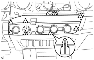
(b) Disconnect the connectors to remove the air conditioning control assembly.
10. REMOVE ENGINE SWITCH
Click here
11. REMOVE TRANSFER POSITION SWITCH (for 4WD)
Click here
 Installation
INSTALLATION
PROCEDURE
1. INSTALL TRANSFER POSITION SWITCH (for 4WD)
Click here
2. INSTALL ENGINE SWITCH
Click here
3. INSTALL AIR CONDITIONING CONTROL ASSEMBLY
(a) Connect the connectors.
...

Other materials:
Removal
REMOVAL
CAUTION / NOTICE / HINT
Text in Illustration
*a
Object Exceeding Weight Limit of Transmission Jack
Be sure to perform this procedure with several people as the rear differential
carrier assembly is very heavy.
Be sure to follow the procedure ...
Turn Signal Switch Circuit
DESCRIPTION
The combination meter assembly receives the turn signal switch information and
controls the turn signal lights.
WIRING DIAGRAM
PROCEDURE
1.
READ VALUE USING TECHSTREAM (TURN SIGNAL SWITCH)
(a) Connect the Techstream to the DLC3.
(b) Turn the igni ...
Operation Check
OPERATION CHECK
1. NOTICE WHEN CHECKING FOLLOWING
(a) Wireless door lock/unlock function:
This wireless door lock control function operates only when the following 3 conditions
are met:
(1) The engine switch is off.
(2) All doors are closed.
(3) The power door lock control system is operatin ...
