Toyota Tacoma (2015-2018) Service Manual: System Diagram
SYSTEM DIAGRAM
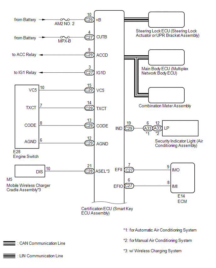
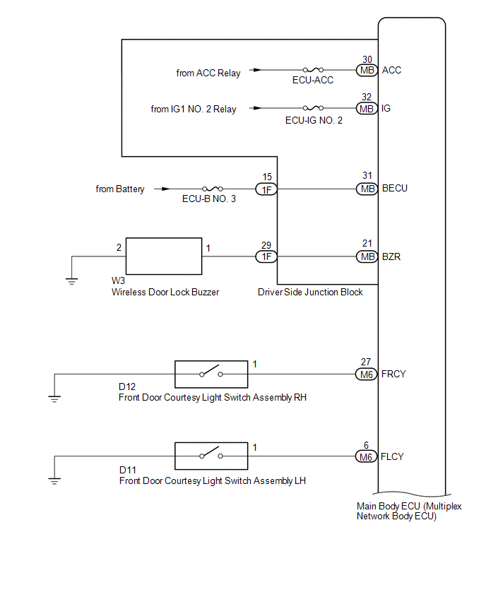
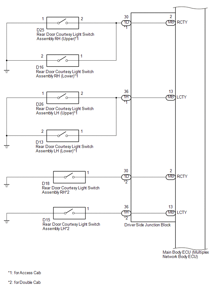
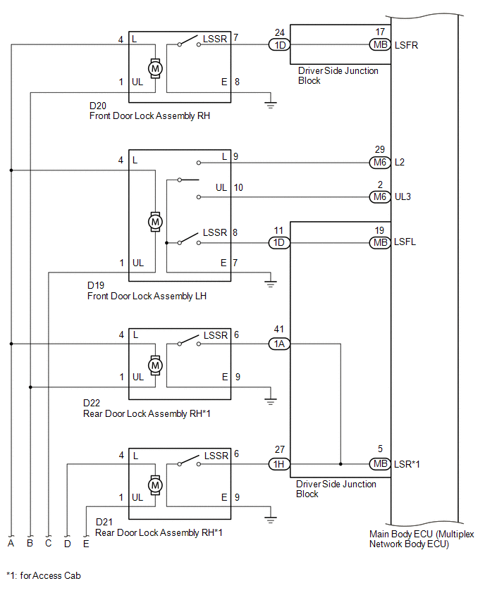
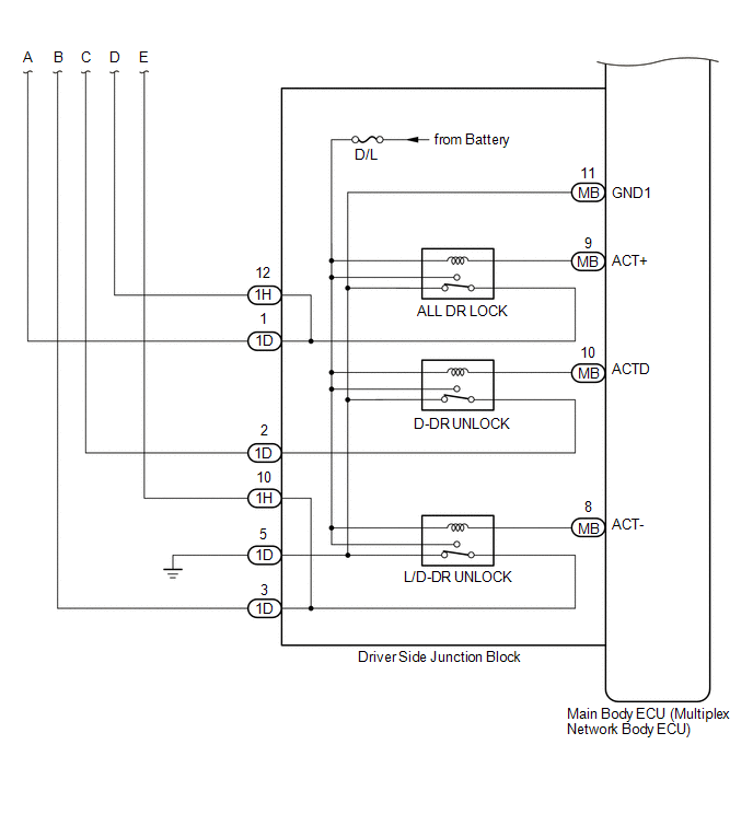
This is a detailed diagram related to the main body ECU (multiplex network body ECU).
|
Component |
Function |
|---|---|
|
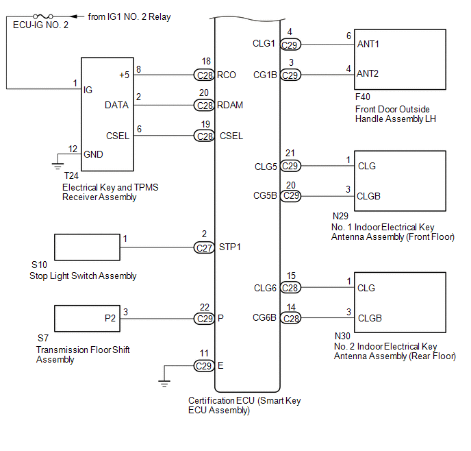
Front door outside handle assembly LH |
Receives request signals from the certification ECU (smart key ECU assembly) via the built-in electrical key antenna (front door) and forms the vehicle exterior detection area. Uses the built-in touch sensor (lock sensor/unlock sensor) to detect the operation of the front door outside handle assembly and sends signals to the certification ECU (smart key ECU assembly). |
|
No. 1 indoor electrical key antenna assembly (front floor) No. 2 indoor electrical key antenna assembly (rear floor) |
Receives the request code from the certification ECU (smart key ECU assembly) and forms the vehicle interior detection area. |
|
Electrical key and TPMS receiver assembly |
Receives the smart key system code/wireless code sent from the electrical key transmitter sub-assembly and sends it to the certification ECU (smart key ECU assembly). |
|
Wireless door lock buzzer |
Sounds when warning functions operate in accordance with certification ECU (smart key ECU assembly) control. |
|
Electrical key transmitter sub-assembly |
Sends the ID code upon receiving a request signal. |
|
Certification ECU (smart key ECU assembly) |
Sends request codes to each electrical key antenna. Distinguishes and verifies the ID code from the electrical key transmitter sub-assembly and sends signals to each ECU in response to operated functions (controls entire system). Performs encryption code communication with the steering lock ECU (steering lock actuator or UPR bracket assembly) when ignition operations are performed. |
 Precaution
PRECAUTION
1. CAUTION REGARDING INTERFERENCE WITH ELECTRONIC DEVICES
CAUTION:
People with implantable cardiac pacemakers, cardiac resynchronization
therapy-pacemakers or implantable car ...
 How To Proceed With Troubleshooting
CAUTION / NOTICE / HINT
HINT:
Use these procedures to troubleshoot the smart key system (for Entry
Function).
*: Use the Techstream.
PROCEDURE
1.
VEHIC ...
Other materials:
Vehicle Speed Tolerance Malfunction (C1AA2)
DESCRIPTION
The forward recognition camera receives vehicle speed tolerance signals from
the combination meter assembly. If the combination meter assembly detects a vehicle
speed tolerance malfunction signal, it informs the forward recognition camera via
CAN communication, and DTC C1AA2 is st ...
Engine compartment
2.7 L 4-cylinder (2TR-FE) engine
1. Washer fluid tank
2.Radiator cap
3.Engine coolant reservoir
4. Engine oil filler cap
5. Power steering fluid reservoir
6. Engine oil level dipstick
7. Brake fluid reservoir
8. Fuse box
9. Battery
10. Condenser
11. Radiator
4.0 L V6 (1GR-FE) engine
...
Front Camera Module Circuit (C1AA0)
DESCRIPTION
When an internal malfunction is detected in the forward recognition camera, DTC
C1AA0 is stored.
DTC No.
Detection Item
DTC Detection Condition
Trouble Area
C1AA0
Front Camera Module Circuit
3 seconds ...
