Toyota Tacoma (2015-2018) Service Manual: On-vehicle Inspection
ON-VEHICLE INSPECTION
PROCEDURE
1. CHECK BATTERY CONDITION
NOTICE:
If the battery is weak or if the engine is difficult to start, recharge the battery and perform inspections again before returning the vehicle to the customer.
(a) Check the battery for damage or deformation. If severe damage, deformation or leakage is found, replace the battery.
(b) Check the electrolyte level in each cell.
- If the electrolyte quantity is below the lower line, replace the battery.
- If the electrolyte quantity is above the lower line, check the battery voltage when cranking the engine. If the voltage is below 9.6 V, recharge or replace the battery.
HINT:
Before checking the battery voltage, turn off all the electrical systems (headlights, blower motor, rear defogger, etc.).
(c) Check the voltage.
(1) Turn the ignition switch off and turn on the headlights for 20 to 30 seconds. This will remove the surface charge from the battery.
(2) Measure the battery voltage according to the value(s) in the table below.
Standard Voltage:
|
Tester Connection |
Condition |
Specified Condition |
|---|---|---|
|
Positive (+) terminal - Negative (-) terminal |
20°C (68°F) |
12.5 to 12.9 V |
If the result is not as specified, recharge or replace the battery.
2. INSPECT BATTERY TERMINAL AND FUSIBLE LINK AND FUSE
(a) Check whether the battery terminals and engine wire harness are loose or corroded.
Torque:
Positive (+) Battery Terminal :
5.4 N·m {55 kgf·cm, 48 in·lbf}
Negative (-) Battery Terminal :
5.4 N·m {55 kgf·cm, 48 in·lbf}
(b) Measure the resistance of the fuses.
Standard resistance:
Below 1 Ω
If the result is not as specified, replace the fuse.
3. INSPECT FAN AND GENERATOR V BELT
(See page .gif) )
)
4. INSPECT GENERATOR WIRING
(a) Visually check the generator wiring.
(1) Check that the wiring is in good condition.
5. CHECK FOR ABNORMAL NOISES
(a) Listen for abnormal noises from the generator assembly.
(1) Check that no abnormal noises are heard from the generator assembly while the engine is running.
If noise occurs, refer to Problem Symptoms Table (See page
).
6. INSPECT CHARGE WARNING LIGHT CIRCUIT
(a) Turn the ignition switch to ON. Check that the charge warning light comes on.
(b) Start the engine and check that the light goes off.
If the light does not operate as specified, troubleshoot the charge warning light circuit.
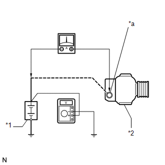
7. INSPECT CHARGING CIRCUIT WITHOUT LOAD
|
(a) Connect a voltmeter and an ammeter to the charging circuit as follows. Text in Illustration
HINT: If the battery/generator assembly tester is available, connect the tester to the charging circuit in accordance with the manufactures instruction. (1) Disconnect the wire from terminal B of the generator assembly and connect it to the negative (-) lead of an ammeter. (2) Connect an ammeter positive (+) lead to terminal B of the generator assembly. (3) Connect a voltmeter positive (+) lead to terminal B of the generator assembly. (4) Ground a voltmeter negative (-) lead. |
|
(b) Check the charging circuit.
(1) Maintain the engine speed at 2000 rpm and check the readings on an ammeter and voltmeter.
Standard current:
10 A or higher
Standard voltage:
13.2 to 14.8 V
If the result is not as specified, repair or replace the generator assembly.
8. INSPECT CHARGING CIRCUIT WITH LOAD
(a) With the engine running at 2000 rpm, turn the high beam headlights on and turn the heater blower switch to the "HI" position.
(b) Check the reading on an ammeter.
Standard current:
30 A or higher
If an ammeter reading is not as specified, repair or replace the generator assembly.
HINT:
If the battery is fully charged, the reading will sometimes be less than the standard. If this is the case, add more electrical load (operate the wipers, rear window defogger, etc.) and check the reading on an ammeter again.
9. INSPECT CHARGING SYSTEM
(a) Check the harness and connector.
(1) Disconnect the E9 ECM connector.
(2) Disconnect the G2 generator assembly connector.
(3) Measure the resistance according to the value(s) in the table below.
Standard Resistance:
|
Tester Connection |
Condition |
Specified Condition |
|---|---|---|
|
E9-34 (LIN) - G2-2 (LIN) |
Always |
Below 1 Ω |
|
E9-34 (LIN) or G2-2 (LIN) - Body ground |
Ignition switch off (while LIN communication is stopped) |
10 kΩ or higher |
If the result is not as specified, repair or replace the harness or connector.
 Diagnostic Trouble Code Chart
DIAGNOSTIC TROUBLE CODE CHART
Charging System
DTC Code
Detection Item
Warning Indicate
Memory
SAE
See page
P161A87
...
 Lost Communication with Alternator Missing Message (P161A87)
DESCRIPTION
The ECM communicates with the generator assembly via LIN communication. If a
LIN communication error is detected, the ECM stores this DTC.
DTC No.
DTC Detection C ...
Other materials:
Removal
REMOVAL
PROCEDURE
1. PRECAUTION
NOTICE:
After turning the engine switch off, waiting time may be required before disconnecting
the cable from the battery terminal. Therefore, make sure to read the disconnecting
the cable from the battery terminal notice before proceeding with work.
Click he ...
Data List / Active Test
DATA LIST / ACTIVE TEST
1. READ DATA LIST
HINT:
Using the Techstream to read the Data List allows the values or states of switches,
sensors, actuators and other items to be read without removing any parts. This non-intrusive
inspection can be very useful because intermittent conditions or sig ...
Parts Location
PARTS LOCATION
ILLUSTRATION
*A
for Hydraulic Brake Booster
*B
for Vacuum Brake Booster
*1
FORWARD RECOGNITION CAMERA
*2
MILLIMETER WAVE RADAR SENSOR ASSEMBLY
*3
HYDRAULIC BRA ...
