Toyota Tacoma (2015-2018) Service Manual: Open in Outer Mirror Indicator(Slave) (C1AB5)
DESCRIPTION
This DTC is stored when the blind spot monitor sensor RH detects an open in the blind spot monitor indicator RH.
|
DTC Code |
DTC Detection Condition |
Trouble Area |
|---|---|---|
|
C1AB5 |
With the blind spot monitor main switch assembly (warning canceling switch assembly) on, the current flowing to the indicator is below a specified value when indicator operation voltage is sent to the indicator. |
|
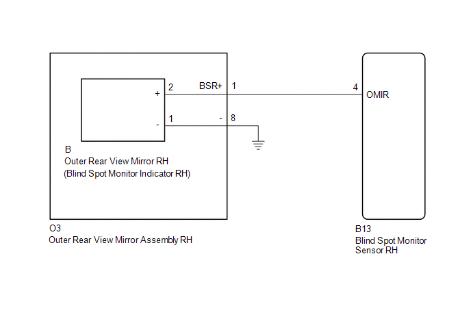
WIRING DIAGRAM
CAUTION / NOTICE / HINT
NOTICE:
When checking for DTCs, make sure that the blind spot monitor main switch assembly (warning canceling switch assembly) is on.
PROCEDURE
|
1. |
CHECK DTC |
(a) Clear the DTCs (See page .gif) ).
).
(b) Recheck for DTCs and check if the same DTC is output again (See page
).
OK:
No DTCs are output.
| OK | .gif) |
USE SIMULATION METHOD TO CHECK |
|
.gif)
|
2. |
CHECK HARNESS AND CONNECTOR (OUTER REAR VIEW MIRROR ASSEMBLY RH - BLIND SPOT MONITOR SENSOR RH AND BODY GROUND) |
(a) Disconnect the B13 blind spot monitor sensor RH connector.
(b) Disconnect the O3 outer rear view mirror assembly RH connector.
(c) Measure the resistance according to the value(s) in the table below.
Standard Resistance:
|
Tester Connection |
Condition |
Specified Condition |
|---|---|---|
|
B13-4 (OMIR) - O3-1 (BSR+) |
Always |
Below 1 Ω |
|
O3-8 - Body ground |
Always |
Below 1 Ω |
| NG | |
REPAIR OR REPLACE HARNESS OR CONNECTOR |
|
|
3. |
INSPECT OUTER REAR VIEW MIRROR ASSEMBLY RH |
(a) Remove the outer rear view mirror assembly RH (See page
).
(b) Remove the outer rear view mirror RH (See page
).
(c) Measure the resistance according to the value(s) in the table below.
Standard Resistance:
|
Tester Connection |
Condition |
Specified Condition |
|---|---|---|
|
O3-1 (BSR+) - B-2 (+) |
Always |
Below 1 Ω |
|
O3-8 - B-1 (-) |
Always |
Below 1 Ω |
| NG | |
REPLACE OUTER REAR VIEW MIRROR ASSEMBLY RH |
|
|
4. |
CHECK OUTER REAR VIEW MIRROR RH |
(a) Replace the outer rear view mirror RH with a new or normally functioning
one (See page ).
(b) Clear the DTCs (See page ).
(c) Recheck for DTCs and check if the same DTC is output again (See page
).
OK:
No DTCs are output.
| OK | |
END (OUTER REAR VIEW MIRROR RH WAS DEFECTIVE) |
| NG | |
REPLACE BLIND SPOT MONITOR SENSOR RH |
 Blind Spot Monitor Slave Module (C1AB7)
DESCRIPTION
This DTC is stored when the blind spot monitor sensor RH detects an internal
malfunction.
DTC Code
DTC Detection Condition
Trouble Area
...
 Blind Spot Monitor Master Module (C1AB6)
DESCRIPTION
This DTC is stored when the blind spot monitor sensor LH detects an internal
malfunction.
DTC Code
DTC Detection Condition
Trouble Area
...
Other materials:
Do-it-yourself service precautions
If you perform maintenance yourself, be sure to follow the correct procedures
as given in these sections.
CAUTION
The engine compartment contains many mechanisms and fluids that may move suddenly,
become hot, or become electrically energized. To avoid death or serious injury observe
the ...
Front Right Seat Heat Sensor Circuit (B14C0)
DESCRIPTION
Output to the front seat cushion heater assembly RH temperature sensor stops
if one of the following occurs: 1) the temperature sensor is open or shorted; or
2) the temperature sensor is damaged and its output value does not change.
DTC Code
DTC Detection Cond ...
Precaution
PRECAUTION
1. IGNITION SWITCH EXPRESSIONS
(a) The type of ignition switch used on this model differs according to the specifications
of the vehicle. The expressions listed in the table below are used in this section.
Expression
Ignition Switch (Position)
Engine ...
