Toyota Tacoma (2015-2018) Service Manual: System Diagram
SYSTEM DIAGRAM
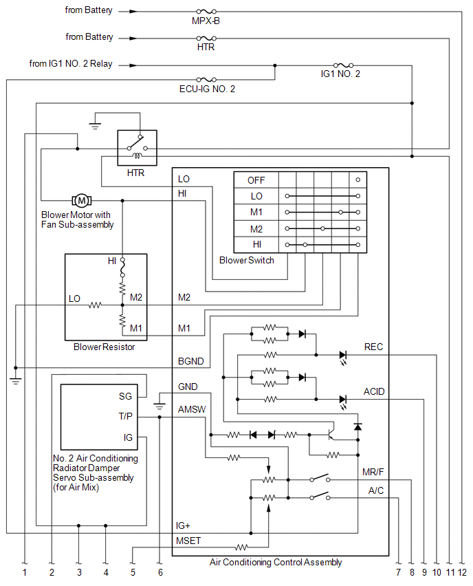
 System Description
SYSTEM DESCRIPTION
1. GENERAL
(a) The air conditioning system has the following controls.
Control
Outline
Manual Control
The air conditioner amplif ...
 Problem Symptoms Table
PROBLEM SYMPTOMS TABLE
HINT:
Use the table below to help determine the cause of problem symptoms.
If multiple suspected areas are listed, the potential causes of the symptoms
are lis ...
Other materials:
Steering Lock Position Signal Circuit Malfunction (B2285)
DESCRIPTION
This DTC is stored when the steering lock position signal sent by the steering
lock ECU (steering lock actuator or upr bracket assembly) via direct line and the
steering lock position signal sent via LIN communication do not match.
HINT:
When the cable is disconnected and reconnec ...
Components
COMPONENTS
ILLUSTRATION
*A
for Type A
*B
for Type B
*C
for Type C
-
-
*1
MILLIMETER WAVE RADAR SENSOR ASSEMBLY
*2
MILLIMETER WAVE RADAR WIRE
...
IG2 Signal Malfunction (B2788)
DESCRIPTION
This DTC is stored when the steering lock ECU (steering lock actuator or UPR
bracket assembly) detects an IG2 power supply malfunction.
HINT:
The steering lock ECU (steering lock actuator or UPR bracket assembly) is not
connected to the CAN communication system. However, the steer ...
