Toyota Tacoma (2015-2018) Service Manual: Fuel Main Valve
Components
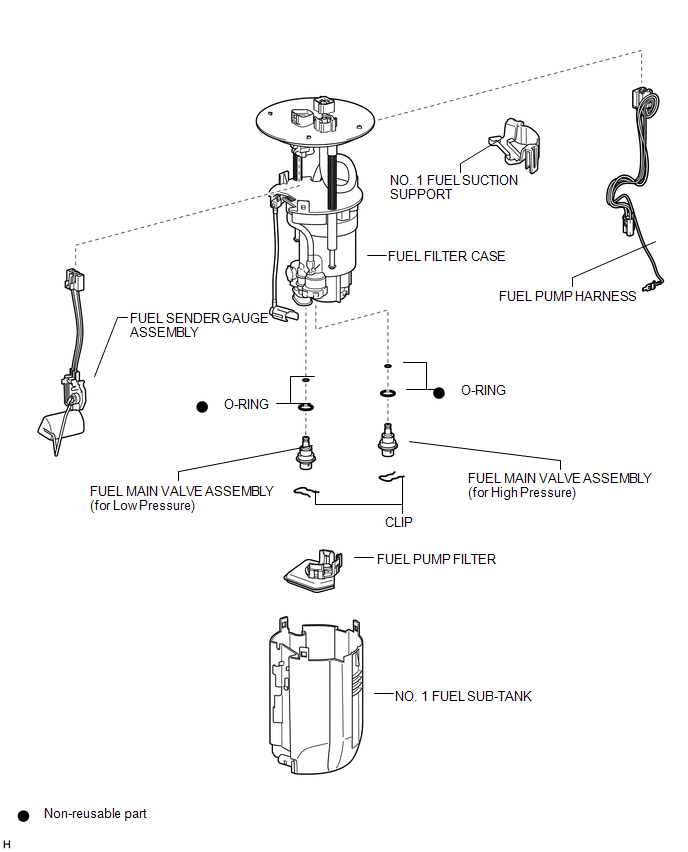
COMPONENTS
ILLUSTRATION
Removal
REMOVAL
PROCEDURE
1. REMOVE FUEL SUCTION TUBE WITH PUMP AND GAUGE ASSEMBLY
(See page .gif) )
)
2. REMOVE FUEL SENDER GAUGE ASSEMBLY
3. REMOVE NO. 1 FUEL SUB-TANK
4. REMOVE FUEL PUMP FILTER
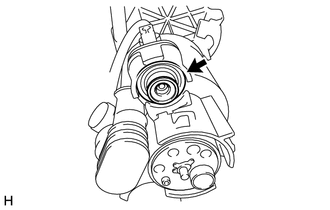
5. REMOVE FUEL MAIN VALVE ASSEMBLY
(a) Remove the fuel main valve assembly (for High Pressure).
|
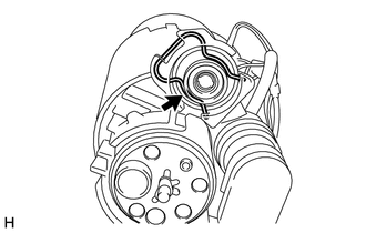
(1) Remove the clip from the fuel filter case. |
|
|
(2) Using a screwdriver, remove the fuel main valve assembly from the fuel filter case. NOTICE: Do not damage the fuel filter case. |
|
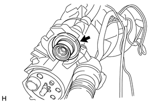
(3) Remove the 2 O-rings from the fuel main valve assembly.
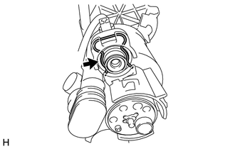
(b) Remove the fuel main valve assembly (for Low Pressure).
|
(1) Remove the clip from the fuel filter case. |
|
|
(2) Using a screwdriver, remove the fuel main valve assembly from the fuel filter case. NOTICE: Do not damage the fuel filter case. |
|
(3) Remove the 2 O-rings from the fuel main valve assembly.
Installation
INSTALLATION
PROCEDURE
1. INSTALL FUEL MAIN VALVE ASSEMBLY
(a) Apply gasoline to 2 new O-rings. Then install the 2 O-rings to the fuel main valve assembly (for Low Pressure).
(b) Apply gasoline to 2 new O-rings. Then install the 2 O-rings to the fuel main valve assembly (for High Pressure).
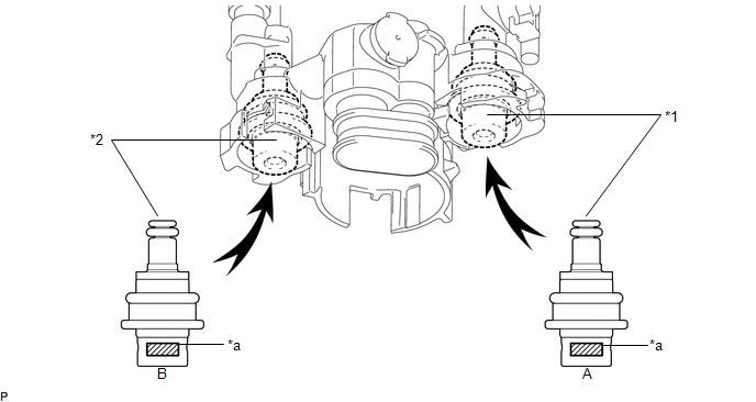
(c) Install the 2 fuel main valve assemblies to the fuel filter case.
NOTICE:
- When installing the O-rings, make sure they do not become pinched or cut.
- The fuel main valve assembly (for Low Pressure) and fuel main valve assembly (for High Pressure) have identification marks (part numbers). If the parts are installed in the wrong location, the engine may stall. Therefore, make sure to install the parts in the correct location.
 Text in Illustration
|
*1 |
Fuel Main Valve Assembly (for Low Pressure) |
*2 |
Fuel Main Valve Assembly (for High Pressure) |
|
*a |
Identification Mark (Part Number) |
- |
- |
|
A |
Fuel Main Valve Assembly (for Low Pressure) |
23070-31*** |
|
B |
Fuel Main Valve Assembly (for High Pressure) |
23070-36*** |
(d) Install the 2 clips to the fuel filter case.
2. INSTALL FUEL PUMP FILTER
.gif)
3. INSTALL NO. 1 FUEL SUB-TANK
4. INSTALL FUEL SENDER GAUGE ASSEMBLY
5. INSTALL FUEL SUCTION TUBE WITH PUMP AND GAUGE ASSEMBLY
 Installation
INSTALLATION
CAUTION / NOTICE / HINT
HINT:
Perform "Inspection After Repairs" after replacing the fuel injector assembly
(See page ).
PROCEDURE
1. INSTALL FUEL INJECTOR ASSEMBLY
HIN ...
 Fuel Pressure Sensor
Components
COMPONENTS
ILLUSTRATION
Inspection
INSPECTION
PROCEDURE
1. INSPECT FUEL DELIVERY PIPE SUB-ASSEMBLY (FUEL PRESSURE SENSOR)
NOTICE:
Do not remove the fuel pressure senso ...
Other materials:
Malfunction of ID-BOX Recognition (B278D)
DESCRIPTION
When the certification ECU (smart key ECU assembly) detects an input signal indicating
that the vehicle is equipped with an ID code box even though the ID code box is
not registered, the certification ECU (smart key ECU assembly) stores this DTC.
DTC Code
DTC ...
Open in Outer Mirror Indicator(Slave) (C1AB5)
DESCRIPTION
This DTC is stored when the blind spot monitor sensor RH detects an open in the
blind spot monitor indicator RH.
DTC Code
DTC Detection Condition
Trouble Area
C1AB5
With the blind spot monitor main switch assembly (warning ...
Installing child restraints
Follow the child restraint system manufacturer’s instructions. Firmly secure
child restraints to the seats using the LATCH anchors or a seat belt. Attach the
top tether strap when installing a child restraint.
The lap/shoulder belt can be used if your child restraint system is not compatible ...
