Toyota Tacoma (2015-2018) Service Manual: System Diagram
SYSTEM DIAGRAM
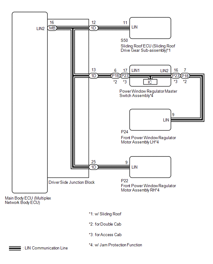
1. DOOR BUS LINES
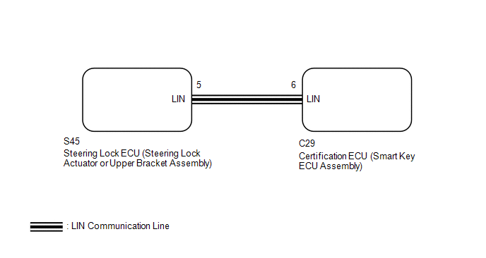
2. CERTIFICATION BUS LINES (w/ Smart Key System)
 System Description
SYSTEM DESCRIPTION
1. LIN COMMUNICATION SYSTEM DESCRIPTION
The LIN communication system is used for communication between the components
in the tables below. If communication cannot be performed t ...
 How To Proceed With Troubleshooting
CAUTION / NOTICE / HINT
HINT:
Use the following procedure to troubleshoot the LIN communication system.
*: Use the Techstream.
PROCEDURE
1.
VEHICLE BROU ...
Other materials:
ABS Warning Light Remains ON
DESCRIPTION
The skid control ECU (brake actuator assembly) is connected to the combination
meter assembly via CAN communication.
If any of the following is detected, the ABS warning light remains on:
The skid control ECU (brake actuator assembly) connectors are disconnected
from the ...
Side doors
The vehicle can be locked/unlocked using the wireless remote control, key or
door lock switch.
■ Wireless remote control (if equipped)
■ Key
Regular Cab models
Locks the door
Unlocks the door
Access Cab and Double Cab models
Locks all doors
Unlocks all doors
Turning ...
AUTO LSD system
The AUTO LSD system aids traction by using the traction control system to control
engine performance and braking when one of the rear wheels begins to spin.
The system should be used only when one of the rear wheels spinning occurs in
a ditch or rough surface.
■ System operation
The sys ...
