Toyota Tacoma (2015-2018) Service Manual: Installation
INSTALLATION
PROCEDURE
1. INSTALL STEERING PAD
(a) Check that the ignition switch is off.
(b) Check that the cable is disconnected from the negative (-) battery terminal.
CAUTION:
Wait at least 90 seconds after disconnecting the cable from the negative (-) battery terminal to disable the SRS system.
(c) Support the steering pad with one hand.
(d) Connect the horn terminal.
|
(e) Connect the 2 airbag connectors. NOTICE: When connecting any airbag connector, take care not to damage the airbag wire harness. |
|
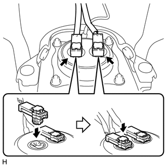
(f) Push in the 2 airbag connector locks to install the 2 airbag connectors.
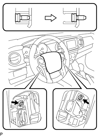
(g) Install the steering pad.
|
(h) Using a T30 "TORX" socket wrench, tighten the 2 screws. Torque: 8.8 N·m {90 kgf·cm, 78 in·lbf} |
|
2. INSTALL LOWER NO. 2 STEERING WHEEL COVER
(a) Engage the guide and claw to install the lower No. 2 steering wheel cover.
3. INSTALL LOWER NO. 3 STEERING WHEEL COVER
(a) Engage the guide and claw to install the lower No. 3 steering wheel cover.
4. CONNECT CABLE TO NEGATIVE BATTERY TERMINAL
Torque:
5.4 N·m {55 kgf·cm, 48 in·lbf}
NOTICE:
When disconnecting the cable, some systems need to be initialized after the cable is reconnected.
Click here .gif)
5. INSPECT STEERING PAD
(a) With the steering pad installed on the vehicle, perform a visual check. If there are any defects as mentioned below, replace the steering pad with a new one:
Cuts, small cracks or marked discoloration on the steering pad top surface or in the grooved portion.
(b) Make sure that the horn sounds.
If the horn does not sound, inspect the horn system.
6. INSPECT SRS WARNING LIGHT
(See page )
 Removal
REMOVAL
PROCEDURE
1. PRECAUTION
CAUTION:
Be sure to read Precaution thoroughly before servicing (See page
).
NOTICE:
After turning the ignition switch off, waiting time may be required before ...
 Theft Deterrent
...
Other materials:
Check Bus 3 Line for Short to +B
DESCRIPTION
There may be a short circuit between one of the CAN bus lines and +B when no
resistance exists between terminal 6 (CA3H) of the central gateway ECU (network
gateway ECU) and terminal 16 (BAT) of the DLC3, or terminal 21 (CA3L) of the central
gateway ECU (network gateway ECU) and t ...
Event data recorder
This vehicle is equipped with an event data recorder (EDR). The main purpose
of an EDR is to record, in certain crash or near crash-like situations, such as
an air bag deployment or hitting a road obstacle, data that will assist in understanding
how a vehicle’s systems performed. The EDR is ...
Radar Cruise Control Presence Determination Malfunction (Engine / HV) (C1A52)
DESCRIPTION
DTC C1A52 is stored when the ECM cannot recognize the millimeter wave radar sensor
assembly.
DTC No.
Detection Item
DTC Detection Condition
Trouble Area
C1A52
Radar Cruise Control Presence Determination Malfuncti ...
