Toyota Tacoma (2015-2018) Service Manual: On-vehicle Inspection
ON-VEHICLE INSPECTION
PROCEDURE
1. INSPECT INSTRUMENT PANEL PASSENGER AIRBAG ASSEMBLY WITHOUT DOOR (for Vehicle not Involved in Collision)
|
(a) Perform a diagnostic system check (See page
|
|
.gif) ).
).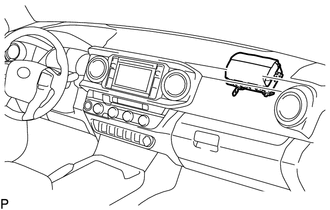
(b) With the instrument panel passenger airbag assembly without door installed on the vehicle, perform a visual check. If there are any defects as mentioned below, replace the instrument panel with a new one:
Cuts, minute cracks or marked discoloration on the instrument panel around the instrument panel passenger airbag assembly without door.
2. INSPECT INSTRUMENT PANEL PASSENGER AIRBAG ASSEMBLY WITHOUT DOOR (for Vehicle Involved in Collision and Airbag has not Deployed)
|
(a) Perform a diagnostic system check (See page
|
|
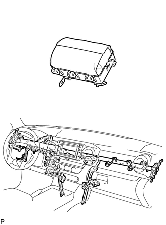
(b) With the instrument panel passenger airbag assembly without door removed from the vehicle, perform a visual check. If there are any defects as mentioned below, replace the instrument panel passenger airbag assembly without door, instrument panel or instrument panel reinforcement with a new one:
- Cuts, minute cracks or marked discoloration on the instrument panel passenger airbag assembly without door.
- Cracks or other damage to the connectors.
- Deformation or cracks on the instrument panel or instrument panel reinforcement.
CAUTION:
For removal and installation procedures of the instrument panel passenger airbag assembly without door, be sure to follow the correct procedure.
 Installation
INSTALLATION
PROCEDURE
1. INSTALL INSTRUMENT PANEL PASSENGER AIRBAG ASSEMBLY WITHOUT DOOR
(a) Engage the 3 hooks (B).
Text in Illustration
*a
Hook ...
 Removal
REMOVAL
PROCEDURE
1. REMOVE INSTRUMENT PANEL SUB-ASSEMBLY
(See page
)
2. REMOVE NO. 3 HEATER TO REGISTER DUCT
3. REMOVE INSTRUMENT PANEL WIRE ASSEMBLY
(a) Using a screwdriver w ...
Other materials:
Front passenger occupant classification system
Your vehicle is equipped with a front passenger occupant classification system.
This system detects the conditions of the right front passenger seat and activates
or deactivates the devices for the front passenger.
1. SRS warning light
2. Front passenger’s seat belt reminder light
3. AIR ...
Mute Signal Circuit between Radio Receiver and Stereo Component Amplifier
DESCRIPTION
This circuit sends a signal to the stereo component amplifier assembly to mute
noise. Because of that, the noise produced by changing the sound source ceases.
If there is an open in the circuit, noise can be heard from the speakers when
changing the sound source.
If there is a sho ...
Security Indicator Light Does not Blink
DESCRIPTION
The certification ECU (smart key ECU assembly) blinks the security indicator
light when the immobiliser is set (engine switch off, or driver door is
opened and closed with engine switch on (IG)).
The certification ECU (smart key ECU assembly) receive the security
...
