Toyota Tacoma (2015-2018) Service Manual: Reassembly
REASSEMBLY
PROCEDURE
1. INSTALL STARTER ARMATURE ASSEMBLY
(a) Install the starter armature to the starter yoke.
2. INSTALL STARTER BRUSH HOLDER ASSEMBLY
(a) Install the starter brush holder assembly.
|
(b) Connect the 4 brushes to the starter brush holder assembly. (1) Using a screwdriver, hold back the brush spring. (2) Connect the brush to the starter brush holder assembly. NOTICE: Check that the positive (+) lead wires are not grounded. |
|
.png)
(c) Place a new O-ring in position on the commutator end frame.
|
(d) Install the commutator end frame with the 2 screws. Torque: 1.5 N·m {15 kgf·cm, 13 in·lbf} |
|
.png)
3. INSTALL MAGNET STARTER SWITCH ASSEMBLY
(a) Apply high-temperature grease to the idle gear, steel ball, return spring, clutch roller and retainer.
|
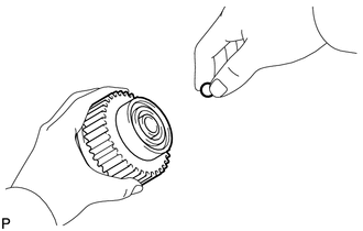
(b) Insert the steel ball into the starter clutch hole. |
|
|
(c) Insert the return spring into the starter clutch hole. Text Illustration
|
|
.png)
(d) Install the starter clutch sub-assembly, idle gear, retainer and clutch roller to the starter drive housing assembly.
|
(e) Install the starter drive housing assembly to the magnet starter switch assembly with the 2 bolts. Torque: 5.9 N·m {60 kgf·cm, 52 in·lbf} |
|
.png)
4. INSTALL STARTER YOKE ASSEMBLY
(a) Install a new O-ring to the groove of the starter yoke assembly.
|
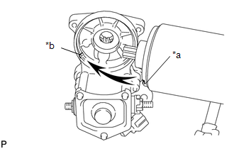
(b) Align the claw of the starter yoke assembly with the groove of the starter switch. Text in Illustration
|
|
|
(c) Install the starter yoke assembly to the magnet starter switch assembly with the 2 bolts. Torque: 5.9 N·m {60 kgf·cm, 52 in·lbf} |
|
.png)
(d) Connect the lead wire to terminal C with the nut.
Torque:
5.9 N·m {60 kgf·cm, 52 in·lbf}
 Installation
INSTALLATION
PROCEDURE
1. INSTALL FLYWHEEL HOUSING SIDE COVER
(a) Install the flywheel housing side cover to the cylinder block sub-assembly.
2. INSTALL STARTER ASSEMBLY
(a) Install the starter a ...
 Starter Relay
Inspection
INSPECTION
PROCEDURE
1. INSPECT STARTER RELAY
(a) Check the resistance.
(1) Measure the resistance according to the value(s) in the table below.
Standard Resistance:
...
Other materials:
Installation
INSTALLATION
PROCEDURE
1. INSTALL TRANSFER POSITION SWITCH (for 4WD)
Click here
2. INSTALL ENGINE SWITCH
Click here
3. INSTALL AIR CONDITIONING CONTROL ASSEMBLY
(a) Connect the connectors.
(b) Engage the 8 clips to install the air conditioning control assembly.
4. INSTALL RADIO AND DISP ...
Unusual Bank Angle Detected (C1440)
DESCRIPTION
If the skid control ECU (brake actuator assembly) determines that the vehicle
is being driven at a steep bank angle, the skid control ECU (brake actuator assembly)
stores DTC C1440 while VSC operation is temporarily disabled.
This is not a malfunction if the system and sensor circu ...
On-vehicle Inspection
ON-VEHICLE INSPECTION
PROCEDURE
1. INSPECT REAR AIRBAG SENSOR (for Vehicle not Involved in Collision)
(a) Perform a diagnostic system check (See page
).
2. INSPECT REAR AIRBAG SENSOR (for Vehicle Involved in Collision and Airbag has
not Deployed)
(a) Perform a diagnostic system check (See p ...
