Toyota Tacoma (2015-2018) Service Manual: System Diagram
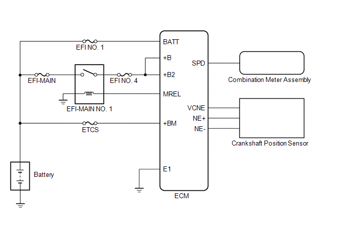
SYSTEM DIAGRAM
 Parts Location
PARTS LOCATION
ILLUSTRATION
ILLUSTRATION
ILLUSTRATION
...
 Check For Intermittent Problems
CHECK FOR INTERMITTENT PROBLEMS
HINT:
Inspect the vehicle ECM using check mode. Intermittent problems are easier to
detect with the Techstream when the ECM is in check mode. In check mode, the ECM ...
Other materials:
Dtc Combination Table
DTC COMBINATION TABLE
HOW TO INTERPRET COMMUNICATION DTCS (DTCS THAT START WITH U)
(a) If a CAN communication error cannot be reproduced, determine the suspected
malfunctioning part using the DTCs stored in ECUs that are connected to the CAN
buses by following the procedure below.
HINT:
Comm ...
Lost Communication with ECM / PCM "A" (U0100-U0142,U0155)
DESCRIPTION
These DTCs are stored when the clearance warning ECU assembly cannot receive
and recognize several signals via the CAN communication system.
DTC No.
DTC Detection Condition
Trouble Area
U0100
Lost Communication with ECM / P ...
Garage door opener
The garage door opener can be trained to operate garage doors, gates, entry
doors, door locks, home lighting systems, security systems, and other devices.
The garage door opener (HomeLink® Universal Transceiver) is manufactured under
license from HomeLink®.
Training the HomeLink® (for U.S. ...
