Toyota Tacoma (2015-2018) Service Manual: VSC Buzzer Circuit
DESCRIPTION
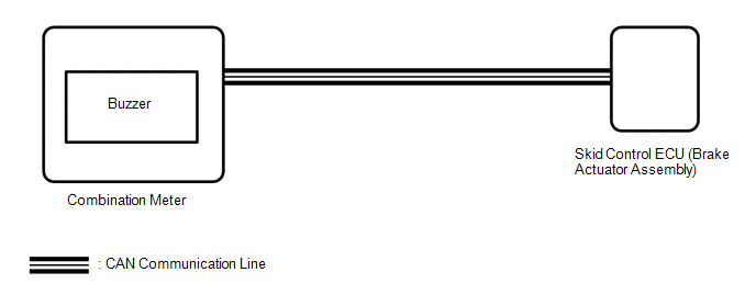
The skid control ECU (brake actuator assembly) is connected to the combination meter via CAN communication.
The combination meter has a built-in VSC warning buzzer:
- Sounds intermittently to inform the driver if the temperature of brake actuator assembly has increased excessively due to continuous operation of AUTO LSD.
- Sounds intermittently to inform the driver that the VSC is operating.
WIRING DIAGRAM
CAUTION / NOTICE / HINT
NOTICE:
When replacing the skid control ECU (brake actuator assembly), perform the zero
point calibration (See page .gif) ).
).
PROCEDURE
|
1. |
CHECK CAN COMMUNICATION LINE |
(a) Turn the ignition switch off.
(b) Connect the Techstream to the DLC3.
(c) Turn the ignition switch to ON.
(d) Turn the Techstream on.
(e) Select CAN Bus Check from the System Selection Menu screen and follow the
prompts on the screen to inspect the CAN bus (See page
).
OK:
CAN Bus Check indicates no malfunctions in CAN communication.
| NG | .gif) |
GO TO CAN COMMUNICATION SYSTEM (HOW TO PROCEED WITH TROUBLESHOOTING) |
|
.gif)
|
2. |
PERFORM ACTIVE TEST USING TECHSTREAM (BUZZER) |
(a) Connect the Techstream to the DLC3.
(b) Turn the ignition switch to ON.
(c) Turn the Techstream on.
(d) Enter the following menus: Chassis / ABS/VSC/TRAC / Active Test.
(e) According to the display on the tester, perform the Active Test.
ABS/VSC/TRAC|
Tester Display |
Test Part |
Control Range |
Diagnostic Note |
|---|---|---|---|
|
Buzzer |
VSC warning buzzer |
Buzzer OFF/ON |
The buzzer can be heard |
(f) Check that the buzzer sounds or stops in accordance with the Techstream.
Result|
Result |
Proceed to |
|---|---|
|
Buzzer does not sound or stop |
A |
|
Buzzer sounds and stops |
B |
| B | |
CHECK FOR INTERMITTENT PROBLEMS (SYMPTOM SIMULATION) |
|
|
3. |
REPLACE COMBINATION METER ASSEMBLY |
(a) Turn the ignition switch off.
(b) Replace the combination meter (See page
).
|
|
4. |
PERFORM ACTIVE TEST USING TECHSTREAM (BUZZER) |
(a) Connect the Techstream to the DLC3.
(b) Turn the ignition switch to ON.
(c) Turn the Techstream on.
(d) Enter the following menus: Chassis / ABS/VSC/TRAC / Active Test.
(e) According to the display on the tester, perform the Active Test.
ABS/VSC/TRAC|
Tester Display |
Test Part |
Control Range |
Diagnostic Note |
|---|---|---|---|
|
Buzzer |
VSC warning buzzer |
Buzzer OFF/ON |
The buzzer can be heard |
(f) Check that the buzzer sounds or stops in accordance with the Techstream.
Result|
Result |
Proceed to |
|---|---|
|
Buzzer does not sound or stop |
A |
|
Buzzer sounds and stops |
B |
| A | |
REPLACE BRAKE ACTUATOR ASSEMBLY |
| B | |
END |
 TC and CG Terminal Circuit
DESCRIPTION
Connecting terminals TC and CG of the DLC3 causes the ECU to display the DTC
by blinking the ABS warning light and slip indicator light.
WIRING DIAGRAM
CAUTION / NOTICE / HINT
NOTI ...
 TS and CG Terminal Circuit
DESCRIPTION
In Test Mode (signal check), a malfunction in the speed sensor that cannot be
detected when the vehicle is stopped can be detected while driving.
Sensor check mode can be entered by co ...
Other materials:
Reporting safety defects for U.S. owners
If you believe that your vehicle has a defect which could cause a crash or could
cause injury or death, you should immediately inform the National Highway Traffic
Safety Administration (NHTSA) in addition to notifying Toyota Motor Sales, U.S.A.,
Inc. (Toll-free: 1-800-331-4331).
If NHTSA rece ...
ABS Control System Malfunction (43)
DESCRIPTION
This DTC is output when the VSC system detects a malfunction in the ABS system.
When DTC 43 is stored, there is no malfunction in the skid control ECU (master cylinder
solenoid).
DTC No.
DTC Detecting Condition
Trouble Areas
43
...
AUTO LSD Indicator Light Remains ON
DESCRIPTION
During normal mode, pressing the VSC OFF switch for a short amount of time changes
vehicle to AUTO LSD mode.
WIRING DIAGRAM
CAUTION / NOTICE / HINT
NOTICE:
When replacing the brake actuator assembly, perform calibration (See page
).
PROCEDURE
1.
CHECK ...
