Toyota Tacoma (2015-2018) Service Manual: Parts Location
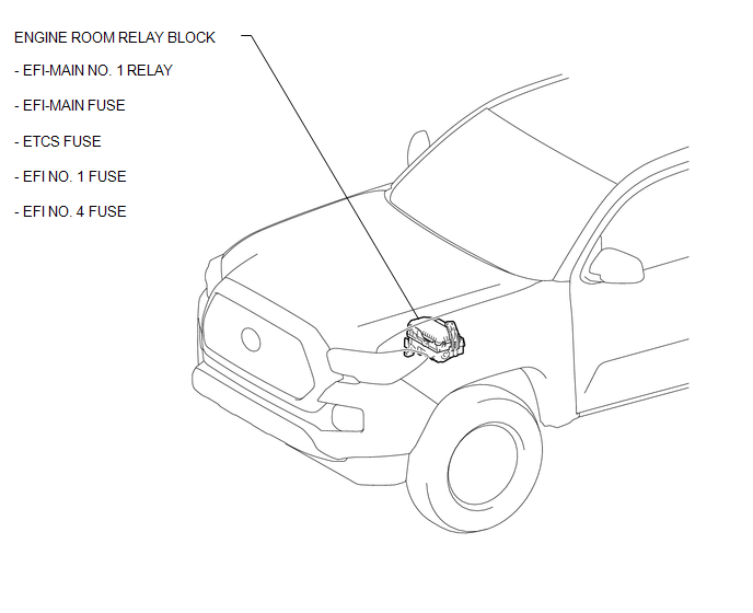
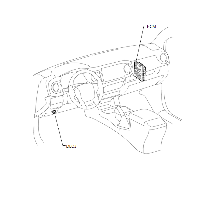
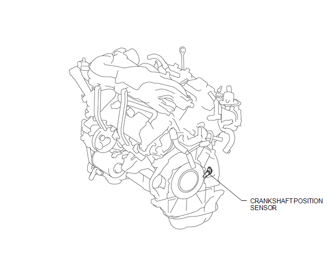
PARTS LOCATION
ILLUSTRATION
ILLUSTRATION
ILLUSTRATION
 Precaution
PRECAUTION
1. INITIALIZATION
NOTICE:
If the ECM is replaced, register the ECU communication ID for Engine
Immobiliser System (See page ).
Perform Registration (VIN registration) wh ...
 System Diagram
SYSTEM DIAGRAM
...
Other materials:
Combination Meter
Components
COMPONENTS
ILLUSTRATION
Removal
REMOVAL
PROCEDURE
1. PRECAUTION
NOTICE:
After turning the ignition switch off, waiting time may be required before disconnecting
the cable from the negative (-) battery terminal. Therefore, make sure to read the
disconnecting the cable fro ...
Disassembly
DISASSEMBLY
PROCEDURE
1. REMOVE CONSOLE COMPARTMENT DOOR CUSHION
HINT:
Use the same procedure as for the opposite side.
(a) Disengage the claw to remove the console compartment door cushion.
2. REMOVE CONSOLE COMPARTMENT DOOR SUB-ASSEMBLY
...
Installation
INSTALLATION
PROCEDURE
1. INSTALL TRANSMISSION FLOOR SHIFT ASSEMBLY
(a) Install the transmission floor shift assembly to the vehicle body with the
4 bolts.
Torque:
14 N·m {143 kgf·cm, 10 ft·lbf}
(b) Attach the 4 clamps to connect the wire harness to the transmission floor
shift assembl ...
