Toyota Tacoma (2015-2018) Service Manual: System Diagram
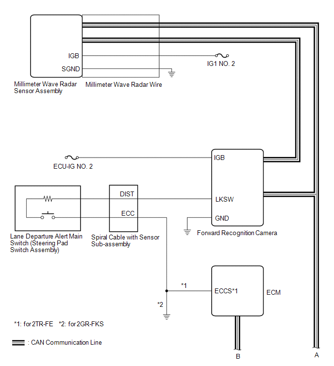
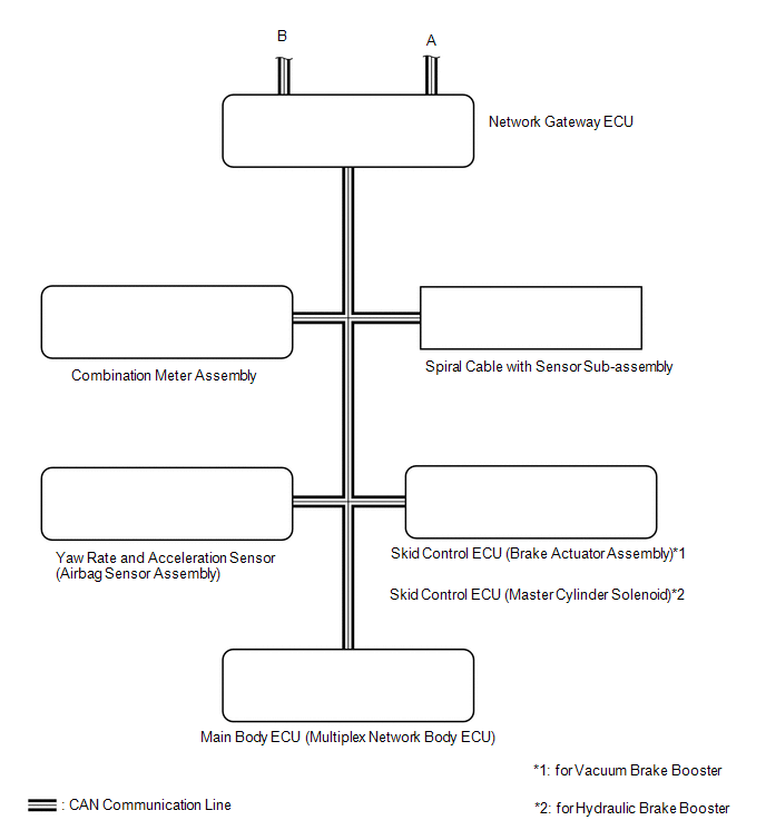
SYSTEM DIAGRAM
 Communication Table
|
Sender ECU |
Receiver ECU |
Signal |
Line |
|---|---|---|---|
| *1: for Vacuum Brake Booster
*2: for Hydraulic Brake Booster |
|||
|
Forward Recognition Camera |
Combination Meter Assembly |
|
CAN |
|
ECM |
Forward Recognition Camera |
|
CAN |
|
|
CAN |
|
|
Combination Meter Assembly |
|
CAN |
|
|
Spiral Cable with Sensor Sub-assembly |
|
CAN |
|
|
Yaw Rate and Acceleration Sensor (Airbag Sensor Assembly) |
|
CAN |
|
|
Main Body ECU (Multiplex Network Body ECU) |
|
CAN |
|
 System Description
SYSTEM DESCRIPTION
LANE DEPARTURE ALERT SYSTEM DESCRIPTION
(a) The lane departure alert system is a system which uses the forward recognition
camera to recognize and determine the lane and the pos ...
 How To Proceed With Troubleshooting
CAUTION / NOTICE / HINT
HINT:
Use these procedures to troubleshoot the lane departure alert system.
*: Use the Techstream.
PROCEDURE
1.
VEHICLE BROUGHT ...
Other materials:
Deck Light Relay
Inspection
INSPECTION
PROCEDURE
1. REMOVE DECK LIGHT RELAY
(a) Check the resistance.
(1) Measure the resistance according to the value(s) in the table below.
Standard:
Tester Connection
Condition
Specified Condition
...
Data List / Active Test
DATA LIST / ACTIVE TEST
NOTICE:
In the table below, the values listed under "Normal Condition" are reference
values. Do not depend solely on these reference values when deciding whether a part
is faulty or not.
HINT:
Using the Techstream to read the Data List allows the values or s ...
Operation Check
OPERATION CHECK
INPUT SIGNAL CHECK
*a
+RES
*b
-SET
*c
ON-OFF
*d
CANCEL
(a) Connect the Techstream to the DLC3.
(b) Check the cruise control main switch using the Data List functio ...
