Toyota Tacoma (2015-2018) Service Manual: System Diagram
SYSTEM DIAGRAM
HINT:
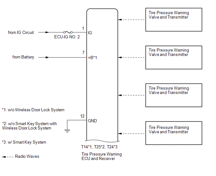
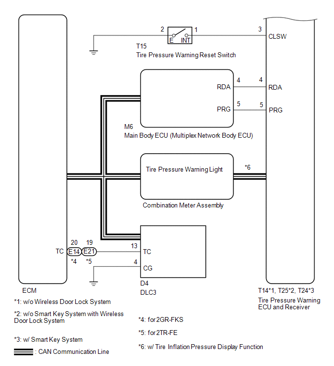
Each tire pressure warning valve and transmitter sends its transmitter ID, temperature and tire pressure information to the tire pressure warning ECU and receiver.
|
Transmitting ECU (Transmitter) |
Receiving ECU |
Signal |
Communication Method |
|---|---|---|---|
|
Combination Meter Assembly |
Main Body ECU (Multiplex Network Body ECU) |
Vehicle speed signal |
CAN communication line |
|
Main Body ECU (Multiplex Network Body ECU) |
Combination Meter Assembly |
Tire pressure warning light signal |
CAN communication line |
 Precaution
PRECAUTION
1. IGNITION SWITCH EXPRESSION
HINT:
The type of ignition switch used on this model differs depending on the specifications
of the vehicle. The expressions listed in the table below are ...
 System Description
SYSTEM DESCRIPTION
1. DESCRIPTION OF SYSTEM
(a) When the tire pressure warning system detects that the tire pressure of a
tire is lower than the threshold, it will inform the driver using a warnin ...
Other materials:
Disassembly
DISASSEMBLY
PROCEDURE
1. REMOVE OIL PUMP RELIEF VALVE
(a) Using a 27 mm socket wrench, remove the oil pump relief valve plug.
(b) Remove the oil pump relief valve spring and oil pump relief valve.
(c) Remove the spring and relief valve.
2. R ...
Reassembly
REASSEMBLY
PROCEDURE
1. INSTALL REAR BUMPER SIDE STAY LH
(a) Install the rear bumper side stay LH with the 2 bolts.
Torque:
30 N·m {306 kgf·cm, 22 ft·lbf}
2. INSTALL REAR BUMPER SIDE STAY RH
HINT:
Use the same procedure as for ...
Freeze Frame Data
FREEZE FRAME DATA
CHECK FREEZE FRAME DATA
HINT:
The ECU records vehicle and driving condition information as freeze frame data
the moment a DTC is stored.
(a) Connect the Techstream to the DLC3.
(b) Turn the ignition switch to ON.
(c) Turn the Techstream on.
(d) Enter the following menus: P ...
