Toyota Tacoma (2015-2018) Service Manual: Terminals Of Ecm
TERMINALS OF ECM
1. CHECK ECM
HINT:
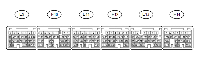
The standard normal voltage between each pair of ECM terminals is shown in the table below. The appropriate conditions for checking each pair of terminals are also indicated. The result of checks should be compared with the standard normal voltage for that pair of terminals, displayed in the Specified Condition column. The illustration above can be used as a reference to identify the ECM terminal locations.
|
Terminal No. (Symbol) |
Wiring Color |
Terminal Description |
Condition |
Specified Condition |
|---|---|---|---|---|
|
E14-2 (BATT) - E11-1 (E1) |
L - W-B |
Battery (for measuring battery voltage and for ECM memory) |
Always |
11 to 14 V |
|
E11-1 (E1) - Body ground |
W-B - Body ground |
Ground circuit of ECM |
Always |
Below 1 Ω |
|
E9-34 (LIN) - Body ground |
L - Body ground |
LIN communication line |
Ignition switch off |
10 kΩ or higher |
 Diagnosis System
DIAGNOSIS SYSTEM
1. DLC3 (Data Link Connector 3)
(a) Check the DLC3 (See page ).
2. BATTERY VOLTAGE
Standard voltage:
11 to 14 V
If the voltage is below 11 V, replace or recharge the battery. ...
 Dtc Check / Clear
DTC CHECK / CLEAR
1. CHECK DTC
(a) Connect the Techstream to the DLC3.
(b) Turn the ignition switch to ON.
(c) Turn the Techstream on.
(d) Enter the following menus: Powertrain / Engine / Trouble ...
Other materials:
On-vehicle Inspection
ON-VEHICLE INSPECTION
PROCEDURE
1. INSPECT AIR CONDITIONER PRESSURE SENSOR (for Automatic Air Conditioning System)
(a) Check the wire harness.
(1) Disconnect the A34 air conditioner pressure sensor connector.
(2) Disconnect the A35 and A36 air conditioning amplifier assembly connector.
...
TC and CG Terminal Circuit
DESCRIPTION
DTC output mode is set by connecting terminals TC and CG of the DLC3.
The DTCs are displayed by blinking the SRS warning light.
HINT:
Make sure that DTCs which relate to the CAN communication system are
not output. If any of these DTCs are output, check the CAN communicat ...
Data List / Active Test
DATA LIST / ACTIVE TEST
DATA LIST
NOTICE:
In the table below, the values listed under "Normal Condition" are reference
values. Do not depend solely on these reference values when deciding whether a part
is faulty or not.
HINT:
Using the Techstream to read the Data List allows the ...
